 Back to ENER-WIN.
Back to ENER-WIN.
The AET App

Flash screen Building plan sketch on the drawing board
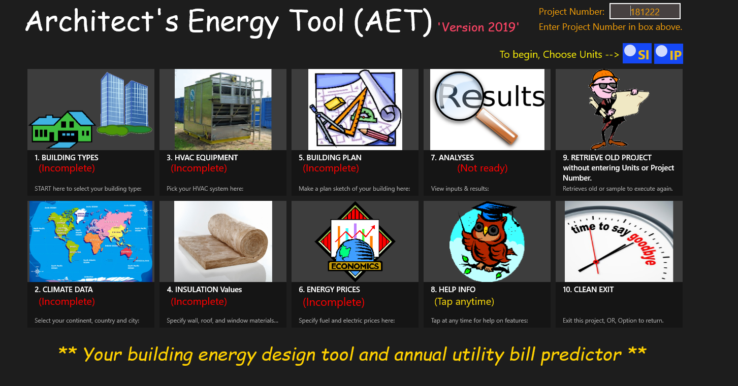
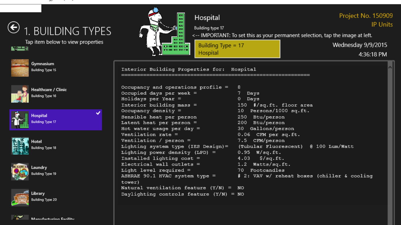
Opening screen Building type selection screen
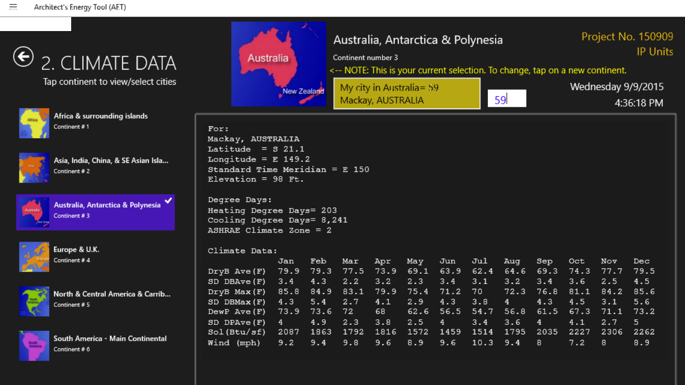
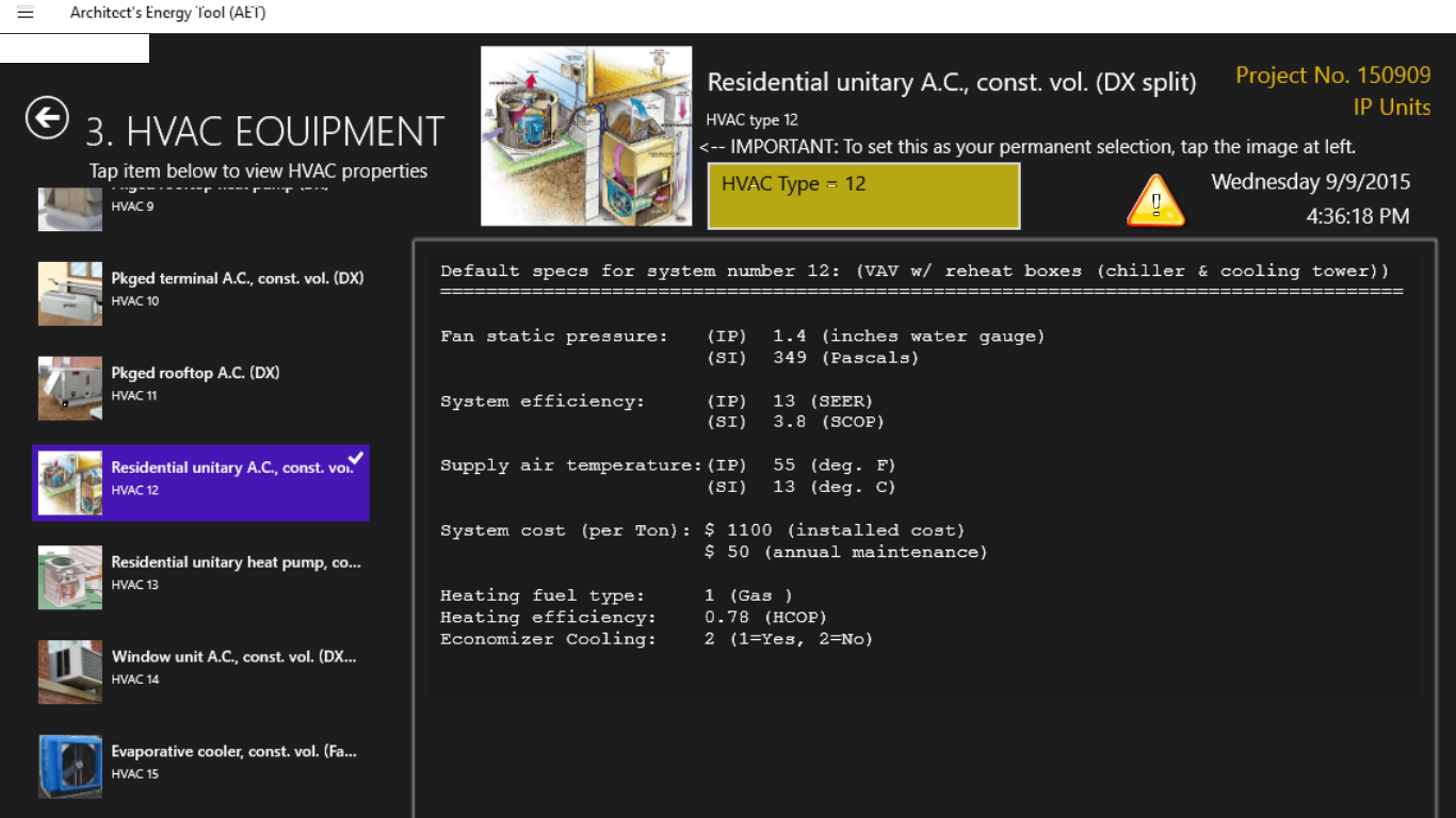
City/Climate selection screen HVAC system type selection screen
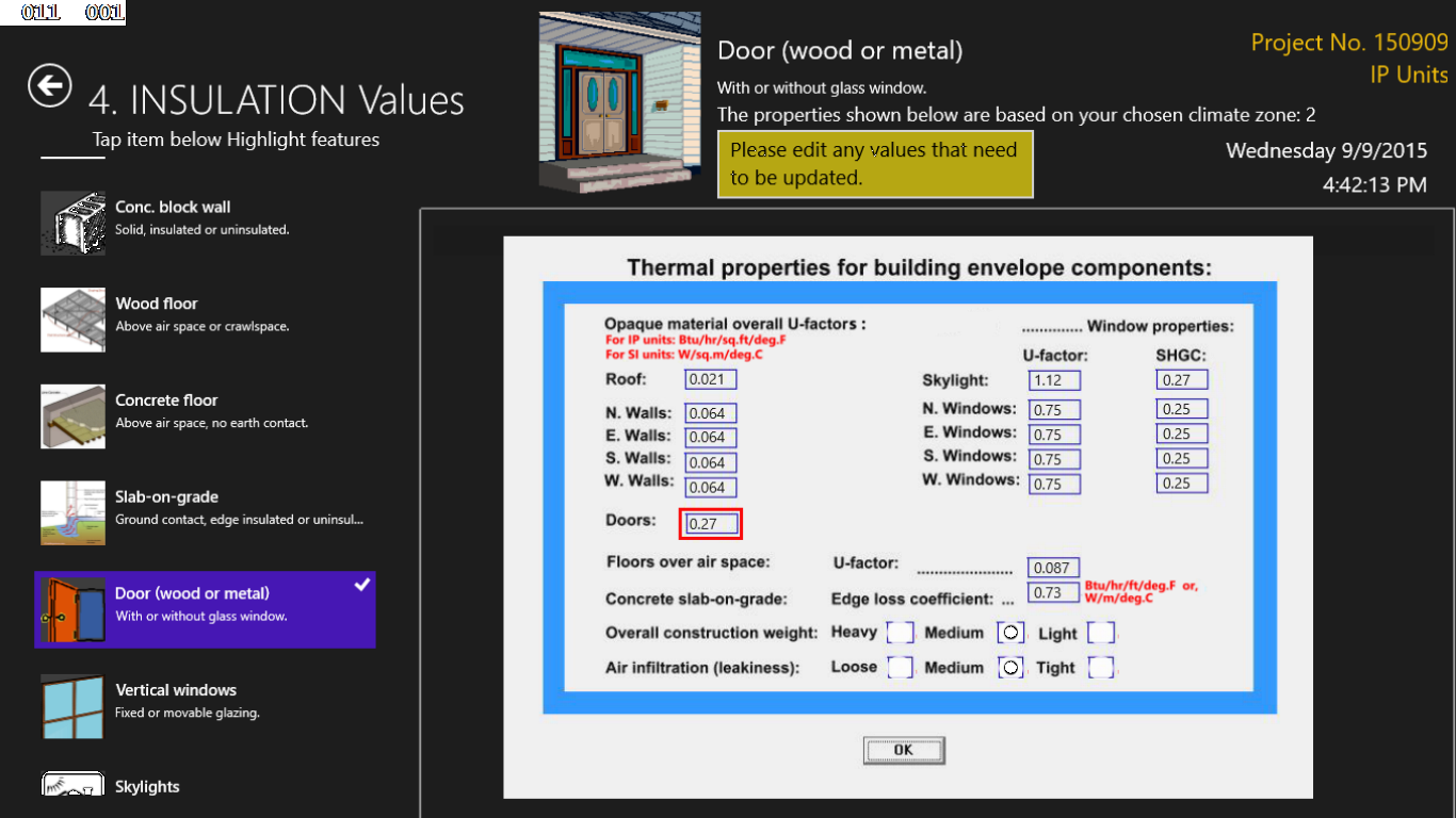
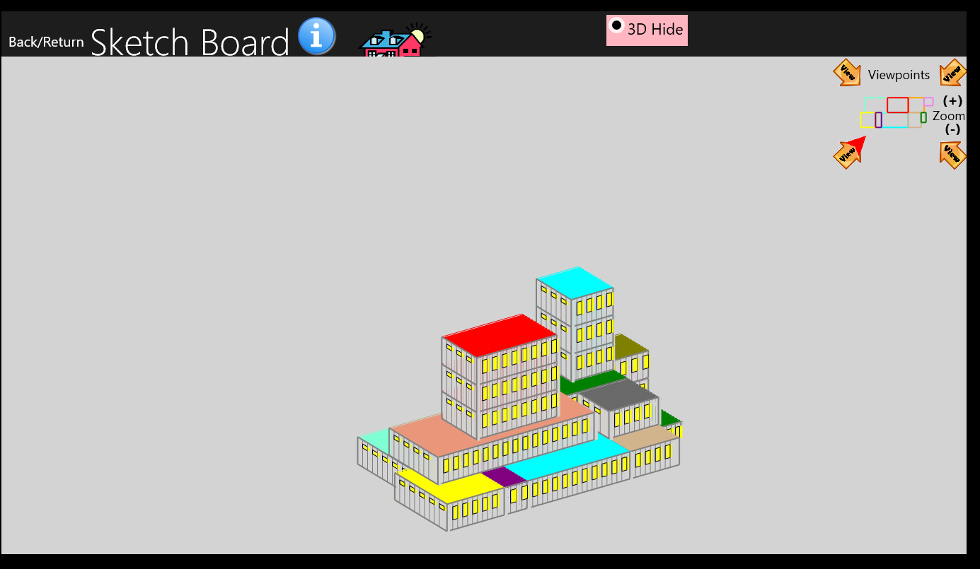
Drawing Insulation selection screen Multi-story 3D Visualization
GENERAL DESCRIPTION:
As a quick tool to help you estimate annual energy consumption and utility bills for your building, the AET tool is intended for home owners as well as architects, engineers, and architectural engineering students to evaluate a building's energy efficiency. In many situations, this tool could be used as a design assistance tool for new buildings or to test the efficiency of an existing building by comparing the program's energy results with the building's actual consumption. This App operates in dual international units of both SI (metric) and IP (British Thermal Units) and uses a current version of an ASHRAE energy standard to set all the building's envelope thermal characteristics, HVAC efficiencies. All parameters are unique to the building type chosen, the climate for your chosen location, and the type of HVAC system chosen. As you start the program, you can choose from 40 different building types (from residential to offices, theatres, schools and sports arenas); 2030 different cities in 6 continents; and 15 different HVAC system types (from window units to ground-source heat pumps, roof-top units, air- and water-cooled chillers, and packaged terminal air distribution systems.
Fuel costs and other economic data are included that are based on defaults in the current energy codes. A rudimentary drawing tool is included, which allows the user to choose from five different drawing board sizes from a 120 x 55 ft. (40 x 18 m.) to a 600 x 275 ft. (180 x 84 m.) drawing surface. Drawing is quick though it is not as rich as any of the popular CAD models. However, users find this model to be a very convenient tool to getting to quick answers. The program also permits infinite recycling of any building changes while always retaining the information as a design progresses.
At several stages of the input, the user should save the current information. The information is saved in text files to your Pictures Library, and these can be printed out later by editing software like Microsoft's NotePad, WordPad, or Word. At five different points in the software, the user can print both the input and the resulting energy summary outputs. There is no waiting for the program to execute results, normally being available is less than 1 second.
Features:
•Quick building energy analyses, quick recycling of input and output results.
•Annual energy consumption and utility bills.
•Graphics tool allows quick design layouts at several different scales to accommodate small to large building projects.
•Ability to draw multi-story buildings and obtain a 3D view from four different view points.
•Printed output results opportunity.
•Includes 40 different building types and climate data for 2033 cities worldwide..
•Energy code-compliant wall/window thermal properties, HVAC units and Lighting levels.
•Full of energy-efficiency defaults to reduce user input burden.
HOW TO OBTAIN THE AET SOFTWARE: The AET App Software can be downloaded from the Microsoft Store for Windows 10 apps. Simply click on Search, and enter "Architect's Energy Tool".TUTORIAL: You can view a Youtube video tutorial by right-clicking here
and selecting "Open link in new tab."
INTRODUCTION:
The building's energy efficiency is shown as an EUI (Energy Use Intensity) in terms of Btus/sq.ft. per year or kWh/sq.m. per year. For comparison purposes, the user is also shown a range of expected EUIs that are typical USA values for the building type being evaluated. The program is full of various defaults that are based on an internationally recognized building energy efficiency standard. By running the software without modifying the thermal parameters, the user can see what the top energy efficiency could be for a building of this type, climate location, and fuel types. Then, the user can modify the thermal characteristics to match his/her real building and then make efficiency comparisons.
Included in the tabulated results are the peak HVAC loads (i.e., the heater and A.C. sizes). This indicates what size equipment should be installed in the building.
The user should be careful about selecting (inputting) the specific building type, the city location, the HVAC system type, drawing of the building plan, and specifying of building interior parameters such as number of occupants, number of typical days of occupancy per week, lighting power levels, appliance (plug) loads, and daily hot water usage per person in the building.
These input parameters are easily done by tapping the eight icons on the main screen in the order suggested, and then tapping specific sub-parameters under each item.
To make it simple for the user, most all of the building parameters are automatically selected by the program after the user selects building type and climate region.
The parameters are set as defaults for building type and climate location based on a well-known energy standard prevalent in the U.S.A.
Items that are not preset are graphical properties: such as, the building area, number of stories, and window areas; however, certain defaults are provided as to reasonable window area percentages. Wall and window thermal characteristics, such as U-Factors (UF) and Solar Heat Gain Coefficients (SHGC), however, are preset based on the climate location chosen.
The energy standard on which the defaults are based is the ASHRAE (American Society of Heating, Refrigerating, and Air-conditioning Engineers) Standards 90.1 and 189.1 (for green buildings.) Certain other defaults are based on the U.S. DOE (Department of Energy) simulation modeling approaches that are in the public domain.
While using the App, the user is shown all these defaulted parameters and is given the opportunity to make changes to any of them that are desired. Changes will most likely force deviation from the energy standard and could result in a less efficient building, but this provides the opportunity to check the energy consumption of the user's intended design or an existing building that is being checked for its efficiency.
Only certain screens will allow for user changes, while others are for information display only. Several of the screens, including the overall energy summary page, can be saved to the Pictures Library under the user's name on his/her computer.
Limitations:
1. This release uses your choice of units, IP (British) or SI (Metric.) You will be required to choose the units type at the beginning of a project, so be careful to observe the defaults that appear on each screen and check to be sure that they are the correct units that you have chosen.2. This App is not an hourly simulation program; therefore, it may not be of great assistance to engineers who are doing energy calibration studies to existing buildings.
3. The methodology is a variable-base degree-hour method that employs a balance temperature concept for calculating the number of degree-hours for heating and cooling above or below the balance temperature.
4. Degree-hours and solar radiation calculations are done for all hours of the day for each month of the year so as to account for the varying sun angles for each daylight hour and for each of the 12 months.
5. The software calculates solar gains on the roof and four walls (including windows) before summing the entire daily solar impacts for both winter and summer months.
6. Climate data are automatically selected from over 2000 cities around the planet. The user first selects the continent, and then scrolls across states or countries to locate the city where the building is located. If the user's city is not included, a nearby city with similar climate should be selected.
Disclaimer:
Use of this software does not guarantee that the results will precisely match any existing building nor will the results exactly predict the annual energy use and utility bill in the future. Temper your expectations with regard to trying to match a computer run with actual building performance.Examples of variables that can result in differences between this model and a real building's performance are: (1) Climate data in the model are based on 30-year long-term records and are most likely different than any future year in which the model is being run, so this is the source of some of the expected discrepancies; (2) Results will typically represent a building designed in compliance with the energy standard, while your building might have less insulation than the standard would require, or it may actually exceed the standard and be more efficient; (3) The building's actual use pattern can be one of the largest sources of differences between simulated and actual buildings. In practice, your building might actually be occupied for less time, lights left on longer (or shorter), and hot water being used less than the default model assumes. Nonetheless, careful inputs will still produce the closest results; and (4) Keep in mind that even the most reliable energy simulation models only come within 10 to 25% of a building's actual energy performance. Notwithstanding all the limitations at play, paying careful attention to the accuracy of the inputs typically will produce reasonably close results of what to expect in the building.
Though the software defaults are based on nationally known standards, none of the software is approved or endorsed by ASHRAE or the U.S. DOE. Publically available data from these two organizations have been incorporated into the program.
Use Sequence:The AET App will require certain inputs to be completed before the user is permitted to input certain other inputs. This does not apply to all parameters, but there are several.
The required sequence is to first enter a project number and select the units. Only after that, you will be able to input the building description in the order shown on the opening screen, i.e.,
(1) Building Type,
(2) Climate Region,
(3) HVAC Types,
(4) Wall/Window types,
(5) Building Sketch,
(6) Economic Data, and
(7) Outputs.(This is where you execute the building energy calculations and view results. If you see a SAVE button at the lower right of the screen, it means you can save the contents to a file in your Pictures Library. )
(8) Exception.. Screen 8 (the tutorial screen) can be opened at any time even before entering a project number.(9) Exception.. Screen 9 (Retrieve old project) can be opened at any time even before entering a project number or units.
Most of the input methods will become self-evident during the navigation from screen to screen. Some require only tapping, while others require typing in of numerical data.
Editing of the default parameters is allowed in the Wall and Window insulation values (screen 4) , the Economic screen (screen 6), and the top portion of the output screens (screen 7, mandatory.) It's important (and required) that the data are inspected very carefully in screen 7, because this is the last opportunity to make changes before an analysis is executed.
The good news is that almost any of the screens can be changed numerous times after the run is executed. This allows the user to inspect any number of variables that might be affecting the annual energy consumption, and make changes if desired. In this way, comparisons of various levels of insulation, various window areas and shading methods, or different HVAC systems can be made.
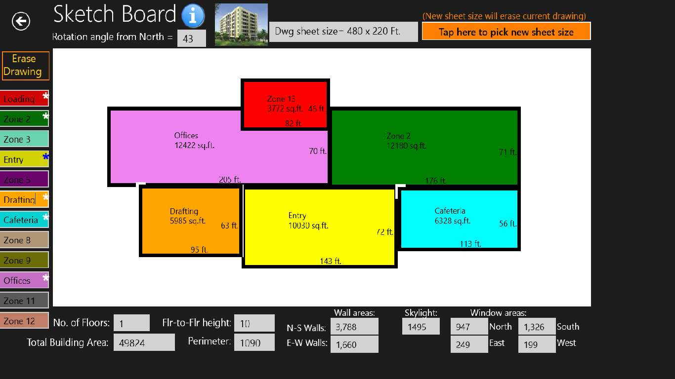
Drawing the building:
The App's sketch routine for inputting the building plan is a rudimentary graphics model that uses streamlined methods to let the user describe a building's orientation, gross floor area, number of floors and areas of walls, roof and perimeter in minimal time. It is not a CAD model, and therefore does not have the rich features of 3D visualization or other 3D features. Basically, it's been kept simple with the goal in mind of speeding up the input process and avoiding hand-calculations by the user.
When the drawing screen is opened, there is an opportunity to open a help screen, which will have most of the instructions explained here.
The first step in the drawing process is to set the orientation of the building by typing a rotation angle in the text box at the top of the drawing screen. The value you type should be the compass bearing of the wall that faces what the program always refers to as North. So, basically, you are telling the program what the "North Wall's" actual bearing angle is in degrees (clockwise) from true North. (Where, 0 = North, 45 = NE, 90 = East, 180 = South, etc.)
To start to draw the building plan, type a room name into any zone box, then click and drag the cursor diagonally on the screen. This forms a dynamic rectangle that constantly updates its horizontal and vertical dimensions (or, in building terms, the length and width of a room. When the desired length and width dimensions are reached, then release the mouse button. At that moment the room's floor area is shown and the total building area is updated. If you find that your planned building will be larger than the dimensions of the drawing sheet, click on the Resize Drawing button. This will erase all rooms that you've drawn so far and return you to the options screen where you can select a larger drawing sheet.
(NOTE: You don't actually have to draw separate rooms/zones. This feature is provided to help you identify or recognize the building's room layouts. If you wish, you can draw the building as one single zone; the results will still be just as accurate.)
During the drawing process, there are some conditions that must be adhered to. Also, be aware that there are certain limitations to the software. To avoid problems and errors in the building energy calculations, please be careful to follow these guidelines:
(1) The limited screen size allows for naming of only 12 zones (or rooms), though up to 24 rooms can be drawn at each building level. The room names above 12 will be automatically be names (zone 13, zone 14, etc., up to zone 24). There can be as many as 15 levels drawn for the multi-story buildings. Each level may have an unlimited number of floors (stories). A zone could be a group of several rooms that have similar thermal characteristics because of their location within the building.
(2) Rooms are always rectangles, but you can allow rooms to overlap, so some zones might be L-shaped or U-shaped. When rooms overlap, the program keeps the full area of the most recently drawn room and subtracts the overlap area from the area of the rooms/zones that it overlapped.
(3) In regard to multistory buildings, the program allows as many floors as desired, but the limitation is that only one floor plan can be drawn. It is recommended that the user make the floor plan as typical as possible for the building, because its layout will be multiplied by the total number of floors.
(4) After all rooms/zones are drawn, enter the window areas for one level only, after which the number of floors can be entered.
(5) After the number of floors is entered, the wall and window areas will be recomputed automatically.
(6) The user is free to edit (override) all areas even after all areas have been computed by the program. This allows the user to account for features that were not possible to compute because of the simplified drawing method. Area changes can even be made to the building's floor area.
(7) The drawing model does not allow for erasing or removal of rooms. If a significant change must be made to the drawing, do not redraw the zone, as this will probably cause the program to add extra floor area that is not actually there. Instead, click on the button that says Erase Drawing. Surprisingly, it's not a major task to start over and redraw your building. Alternatively, if all you want to change are window and wall areas, these can be easily edited as can all other numerical values.
(8) This drawing model does not permit diagonal room arrangements, but the entire building can be rotated by placing a compass bearing in the rotation angle box.
After leaving the sketch screen, the sketch will remain in tact, so if you want to return to it later to make changes, to say, the window areas, you'll find the entire plan and the wall and window areas to still show up accurately. Lastly, you can return to this tutorial at anytime during the processing of a building project. The tutorial does not interfere with the contents of the building project you are working on.