SECTION 5:
EEC-IV QUICK TEST PROCEDURES
The Key On Engine Off and Engine Running Self-Tests detect faults that are present at the time of testing. ...
more
- INTRODUCTION
-
Faults that occur only when the vehicle is operating or intermittent faults that have occurred in the last 80 warm-up cycles are detected during Continuous Self-Test, stored in Continuous Memory an displayed during Key On Engine Off Self-Test
- When directed to a Pinpoint Test, always read the cover page(s) for that test. Read the notes and look carefully at the Pinpoint Test Schematic.
- After service, rerun Quick Test to ensure that service was effective.
- It may be necessary to disconnect or disassemble harness connector assemblies to do some of the inspections. Pin locations should be noted before disassembly.
- VISUAL CHECK
- 1. Inspect the air cleaner and inlet ducting.
- 2. Check all engine vacuum hoses for damage, leaks, cracks, blockage, proper routing, etc.
- 3. Check EEC system wiring harness for proper connections, bent or broken pins, corrosion, loose wires, proper routing, etc.
- 4. Check the Powertrain Control Module (PCM), sensors and actuators for physical damage.
- 5. Check the engine coolant for proper level and mixture.
- 6. Check the transmission fluid level and quality.
- 7. Make all necessary repairs before continuing with QUICK TEST.
- VEHICLE PREPARATION AND EQUIPMENT HOOKUP
- Notes: Refer to the illustrations for Data Link Connector (DLC) pin orientation and VOM, STAR or Scan Tool hookup.
- VEHICLE PREPARATION
- Perform ALL safety steps required to start and run vehicle tests - apply parking brake, put shift lever firmly in PARK position (NEUTRAL on manual transmission), block drive wheels, etc.
- Turn off ALL electrical loads--radios, lights, A/C, heater, blower, fans, etc.
- figure 2
- figure 3
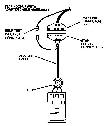
- STAR TESTER
- 1. Turn the ignition key off.
- 2. Connect the color coded adapter cable to the STAR tester.
- 3. Connect the adapter cable leads to the proper connectors (Figure 2).
- 4. Connect the timing light.
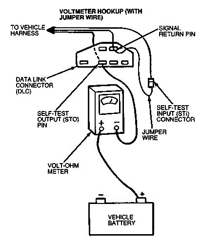
- ANALOG VOLT/OHM METER (VOM)
- 1. Turn the ignition key off.
- 2. Set the VOM on a DC voltage range to read from 0 to 15 volts.
- 3. Connect the VOM from the battery positive post to the Self-Test Output pin of the large Data Link Connector (DLC) (figure 3).
- 4. Connect the timing light.
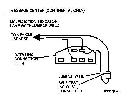
- MALFUNCTION INDICATOR LAMP (MIL)
- No special equipment hookup is required. STI is jumpered to SIG RTN at Self-Test Input (STI) connector and the Data Link Connector (DLC).
- MESSAGE CENTER on Continental Applications Only
- No special equipment hookup is required. STI is jumpered to SIG RTN at Self-Test Input (STI) connector and the Data Link Connector (DLC).
- TRANSMISSION CONTROL INDICATOR LAMP (TCIL) on 7.3L Diesel Engines Only
- No special equipment hookup is required. STI is jumpered to SIG RTN at Self-Test Input (STI) connector and the Data Link Connector (DLC).
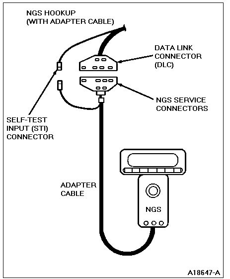
- NEW GENERATION STAR (NGS) SCAN TOOL
- 1. Turn the ignition switch off.
- 2. Connect the appropriate EEC adapter cable to the Scan Tool.
- 3. Connect the adapter leads to the DLC and STI connector.
- 4. Connect the timing light (if applicable).
- For the 3.0L Flex Fuel Taurus, select the 1993 application (version 4.0 release only).
- KEY ON ENGINE OFF SELF-TEST
- NOTES:
- Continuous Memory Diagnostic Trouble Codes (DTCs) recorded in this step will be used for diagnosis after a PASS code 11 or 111 is received in both the Key On Engine Off and the Engine Running Self-Tests.
- Deviation from this procedure may cause the output of false DTCs.
- On all vehicles equipped with a 4.9L ENGINE, the clutch must be depressed during the Key On Engine Off Self-Test.
- On all vehicles equipped with a 7.3L DIESEL ENGINE, the throttle must be depressed (WOT) during the entire Key On Engine Off Self-Test.
- How to run the KEY ON ENGINE OFF SELF-TEST
- 1. Verify that the vehicle has been properly prepared.
- 2. Start engine and run until it reaches operating temperature.
- 3. Turn engine off and wait 10 seconds.
- 4. Activate Self-Test.
- STAR Tester:Latch the center button in the down position.
- Analog VOM: Jumper STI to SIG RTN at the DLC and STI connectors.
- **MALFUNCTION INDICATOR LAMP (MIL)**: Jumper STI to SIG RTN at the DLC and STI connectors. DTCs will be flashed on the Malfunction Indicator Lamp (MIL).
- TRANSMISSION CONTROL INDICATOR LAMP (TCIL) 7.3L Diesel only: Jumper STI to SIG RTN at the DLC and STI connectors. Service Codes will be flashed on the TCIL.
- MESSAGE CENTER (Continental Applications Only). Refer to "Self-Test with Message Center."
- SCAN TOOL: 1) Enter vehicle selection. 2) Enter KOEO Self-Test.
- 5. Place ignition key in the ON position.
- For 7.3L Diesel vehicles only, depress the throttle.
- 6. Record all Diagnostic Trouble Codes (DTCs) displayed.
- DON'T Depress throttle during Key On Engine Off Self-Test on gasoline engine applications.
- ENGINE RUNNING SELF-TEST
- SPECIAL NOTES:
- On vehicles equipped with the Brake On/Off (BOO) circuit, the brake pedal MUST be depressed and released AFTER the ID code.
- On vehicles equipped with the Power Steering Pressure (PSP) switch, within 1 to 2 seconds after the ID code, the steering wheel must be turned at least one-half turn and released.
- On vehicles equipped with E4OD transmission, the Transmission Control Switch (TCS) must be cycled after the ID code.
- The Dynamic Response code is a single pulse (or a 10 code on the STAR Tester) that occurs 6-20 seconds after the engine running identification code. (See Code Output Format in this section.)
- When/if the Dynamic Response code occurs, perform a brief wide open throttle.
- How To Run the ENGINE RUNNING SELF-TEST
- 1. Deactivate Self-Test.
- 2. Start and run engine at 2,000 rpm for two minutes. This action warms up the HO2S.
- 3. Turn engine off, wait 10 seconds.
- 4. Activate Self-Test.
- 5. Start engine.
- 6. After the ID code, depress and release the brake pedal if appropriate. See Special Note on previous page.
- 7. After the ID code, within 1 to 2 seconds, turn the steering wheel at least one-half turn and then release it, if appropriate. See Special Notes above.
- 8. If a Dynamic Response Code occurs, perform a brief wide-open throttle (WOT).
- 9. Record all Diagnostic Trouble Codes (DTCs) displayed.
- DON'T Depress the throttle unless a Dynamic Response code is displayed.
- SELF-TEST DESCRIPTION
- The Self-Test is divided into three specialized tests: Key On Engine Off Self-Test, Engine Running Self-Test, and Continuous Self-Test. The Self-Test is not a conclusive testby itself, but is used as a part of the functional Quick-Test diagnostic procedure. The PCM stores the Self-Test program in permanent memory. When activated, Self-Test checks the EEC system by testing memory integrity and processing capability, and verifies that various sensors and actuators are connected and operating properly.
- The Key On Engine Off and Engine Running Self-Tests are functional tests which only detect faults present at the time of the Self-Test. Continuous Self-Test is performed during normal vehicle operation and stores any fault information in Keep Alive Memory (KAM) for retrieval at a later time.
- KEY ON ENGINE OFF SELF-TEST
- At this time, a test of the EEC system is conducted with power applied and engine at rest. To detect errors during Key On Engine Off Self-Test, the fault must be present at the time of testing.
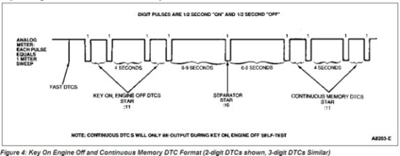
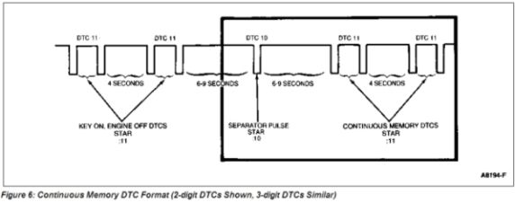
- SEPARATOR PULSE
- A single 1/2 second separator pulse is issued 6-9 seconds after the last Key On Engine Off DTC. Then, 6-9 seconds after the single 1/2 second separator pulse, the Continuous Memory DTCs will be issued.
- CONTINUOUS MEMORY DIAGNOSTIC TROUBLE CODES (DTCs)
- Continuous Memory DTCs are issued as a result of information stored during Continuous Self-Test, while the vehicle was in normal operation. These DTCs are displayed only during Key On Engine Off Self-Test
and after the separator pulse. Intermittent faults that have not occurred in the last 80 warm-up cycles (40 cycles on some applications) are erased from Continuous Memory and will not produce a Continuous Memory DTC.
- NOTE: The separator pulse and Continuous Memory DTCs follow Key On Engine Off DTCs ONLY.
- ENGINE RUNNING SELF-TEST
- At this time, a test of the EEC system is conducted with the engine running. The sensors are checked under actual operating conditions and at normal operating temperatures. The actuators are exercised and checked for expected results.
- ENGINE IDENTIFICATION CODES (ID Codes)
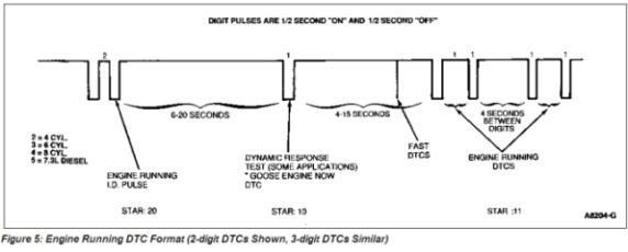
- Engine ID codes are issued at the beginning of the Engine Running Self-Test and are one-digit numbers represented by the number of pulses sent out. For gasoline engines, the engine ID code is equal to one-half the number of engine cylinders (i.e. 2 pulses = 4 cylinders). For the 7.3L Diesel engine, the ID code = 5. These codes are used to verify the proper PCM is installed and that the Self-Test has been entered.
- DYNAMIC RESPONSE CHECK
- The dynamic response check is used on some applications to verify operation of the TP, MAF, MAP and KS sensors during the brief Wide-Open Throttle (WOT) performed during the Engine Running Self-Test. The signal for the operator to perform the brief WOT is a single pulse or 10 code on the STAR Tester.
- POWER STEERING PRESSURE (PSP) SWITCH TEST
- On vehicles equipped with Power Steering Pressure (PSP) switch, the steering wheel must be turned one-half turn and released AFTER the ID Code has been displayed. This tests the ability of the EEC system to detect a change of state in the PSP switch.
- BRAKE ON/OFF TEST
- On vehicles equipped with Brake On/Off (BOO) input, the brake pedal MUST be depressed and released AFTER the ID Code has been displayed. This tests the ability of the EEC system to detect a change of state in the Brakelamp Switch.
- TRANSMISSION CONTROL SWITCH (TCS) TEST
- On vehicles equipped with TCS, the switch must be cycled after the ID code has been displayed. This tests the ability of the EEC system to detect a change of state in the TCS.
- ADAPTIVE FUEL SELF-TEST
- Adaptive fuel logic is used in fuel injection systems primarily to account for normal variability in fuel system components. When the fuel system is detected to be biased rich or lean during steady state vehicle operation, Adaptive Fuel will make a corresponding shift in the fuel delivery calculations so an unbiased condition will exist. The adaptive fuel "shift" is stored in Keep Alive Memory (KAM), which is powered by the vehicle battery. This prevents Adaptive Fuel from being lost when the vehicle is turned off.
- MAF/TP/INJECTOR PULSEWIDTH IN-RANGE SELF-TEST
- The In-Range Self-Test was designed to detect in-range failures of the MAF/TP or fuel delivery systems. The PCM will use information from these three systems to generate three independent values. The three independent values will be continuously monitored. If one of the values differ significantly from the others during normal vehicle operation, a Continuous Memory DTC 121, 124, 125, 184, 185, 186 or 187 will be displayed.
- CODE OUTPUT FORMAT
- The EEC system communicates service information through the Diagnostic Trouble Codes (DTCs). These DTCs are two-digit or three-digit numbers representing the results of Self-Test.
The DTCs are transmitted on the Self-Test Output (STO) circuit found in the Data Link Connector (DLC). They are in the form of timed pulses, and are read by the technician on a voltmeter, STAR tester, Malfunction Indicator Lamp (MIL), Transmission Control Indicator Lamp (TCIL) or on the Continental message center.
- DIAGNOSTIC TROUBLE CODES (DTC) FORMAT
- KEY ON ENGINE OFF AND CONTINUOUS MEMORY DTC's
- ENGINE RUNNING DTCs
- FAST DTCs/SLOW DTCs
- Fast DTCs are issued before slow service DTCs. These DTCs contain the identical information as the slow DTCs, but are transmitted at 100 times the normal rate. These DTCs are interpreted by special equipment at the end of the assembly line by the Body and Assembly Division, as well as the SUPER STAR II tester. After Fast DTCs have been output, Self-Test should not be exited (remove jumper, unlatch button, etc.) until all the Slow DTCs have been output. Exiting before slow DTCs have been output will erase any Continuous Memory DTCs. Some meters in service detect these codes as a short burst of information (slight meter deflection).
- CONTINUOUS SELF-TEST
- The Continuous Memory DTCs are separated from the Key On Engine Off DTCs by a single separator pulse, Figure 6.
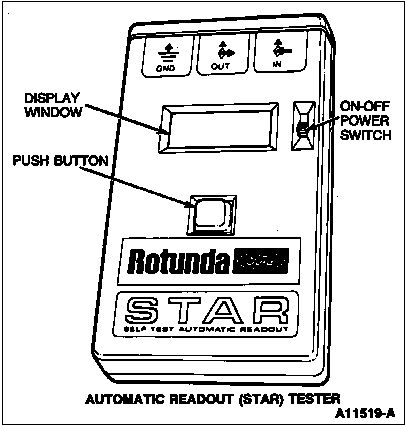
- SELF-TEST WITH AUTOMATIC READOUT (STAR) TESTER
- NOTE: The STAR tester cannot be used to read 3-digit DTCs. If the STAR tester is used on a 3-digit DTC application, the display will be blank.
- After hooking up the STAR tester and turning on the power switch, the tester will run a display check and the numerals 88 will begin to flash in the display window (Figure 7). A steady 00 will then appear, indicating that the STAR tester is ready.
- To receive the DTCs, press the push button at the front of the STAR tester. The button will latch down, and a colon will appear in the display window in front of the 00 numerals. The colon must be displayed to receive the service codes.
- To clear the display window during the Self-Test, turn off the vehicle's engine, press the tester's push button once to unlatch it (colon will disappear), then press the button again to latch down the button (colon will appear again).
- The STAR tester will display the last service code received, even after disconnecting it from the vehicle. It will hold the service code on the display until the power is turned off or the push button is unlatched and relatched.
- For a detailed description of the STAR tester and the variety of tests that can be run, refer to the instruction manual provided with the tester.
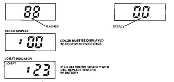
- Figure 7: Star Tester DTC Format
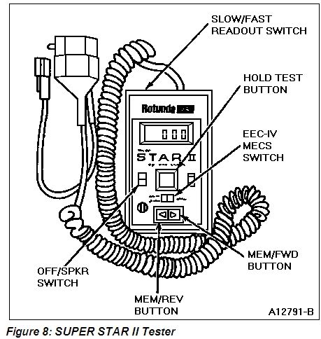
- SELF-TEST WITH SUPER STAR II TESTER
- The SUPER STAR II Tester (Figure 8) can read fast DTCs as well as slow DTCs. A built-in Self-Test memory will retain the DTCs as they are received. The SUPER STAR II tester also contains a beeper for running wiggle tests.
- After hooking up the SUPER STAR II tester and turning it on, the SUPER STAR II will briefly display 888. It will also light all the prompts on the left side of the display and the speaker will beep. When the tester is ready, both the STI-LO and STO-LO will be on, but the readout will be blank if the vehicle key is off.
- KEY ON ENGINE OFF (KOEO) SELF-TEST
- 1. Plug in both connectors of the tester to the mating connectors of the vehicle.
- 2. Determine the type of system you have (EEC-IV or MECS) and set the switch to the proper type.
- 3. Select fast code mode or slow code mode with the mode selector switch.
- NOTE: The SUPER STAR II tester will only display 3-digit DTCs in fast code mode. If slow code mode is used on 3-digit DTC applications, the display will be blank.
- 4. Turn on the power to the tester.
- 5. Depress the test button on the tester to the test position.
- 6. Turn on the vehicle ignition key.
- The tester will now read any DTCs in this mode.
- KEY ON ENGINE RUNNING (KOER) SELF-TEST
- 1. Start and warm up the engine until it is at a normal running temperature.
- 2. Turn the engine off.
- 3. Depress the test button to the test position, then restart the engine.
- On applications with 2-digit DTCs, the tester will display an engine I.D. code, and on certain vehicles, a Dynamic Response code. Then, service codes will be displayed.
- For 3-digit DTC applications, no engine ID code will be displayed. The Dynamic Response indicator will light but no Dynamic Response code will be displayed. DTCs will then be displayed.
- For a detailed description of the variety of tests that can be run with the SUPER STAR II, refer to the instruction manual provided with the tester.
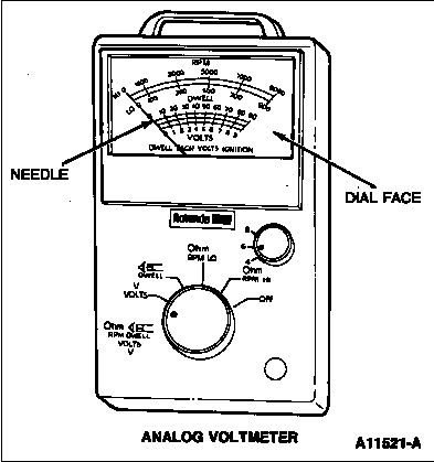
- SELF-TEST WITH ANALOG VOLTMETER
- DTCs will be represented by pulsing or sweeping movements of the voltmeter's needle across the dial face of the voltmeter (Figure 9). A single-digit number of three will be reported by three needle pulses (sweeps). However, a DTC is represented by a two-digit or three-digit number, such as 2-3. As a result, the DTC of 2-3 will appear on the voltmeter as two needle pulses (sweeps). After a two-second pause, the needle will pulse (sweep) three times.
- The Continuous Memory DTCs are separated from the Key On Engine Off DTCs by a six-second delay, a single half-second sweep, and another six-second delay.
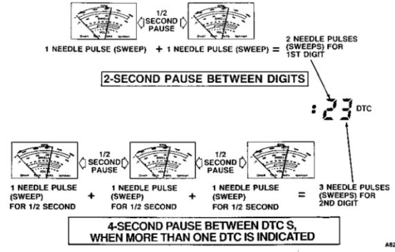
- Figure 9: Analog Voltmeter DTC Format (2-digit DTCs Shown, 3-digit DTCs Similar)
- SELF-TEST WITH MALFUNCTION INDICATOR LAMP (MIL)
- During Self-Test, a DTC is reported by the Malfunction Indicator Lamp (MIL). It will flash the "CHECK ENGINE" or "SERVICE ENGINE SOON" light on the dash panel (Figure 10). A single-digit number of three will be reported by three flashes.
- However, a DTC is represented by a two-digit or three-digit number, such as 2-3 or three digit. As a result, the Self-Test DTC of 2-3 will appear on the MIL as two flashes, then, after a two-second pause, the MIL will flash three times.
- The Continuous Memory DTCs are separated from the Key On Engine Off DTCs by a six-second delay, a single half-second flash, and another six-second delay.
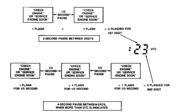
- Figure 10: Malfunction Indicator Lamp (MIL) DTC Format (2-digit DTCs Shown, 3-digit DTCs Similar)
- SELF-TEST WITH MESSAGE CENTER (Continental Only)
- 1. On the Electronic Instrument Cluster (Figure 11), hold in all three buttons (Gauge Select, English Metric and Speed Alarm) at the same time.
- a. Key On Engine Off Self-Test
- While holding in all three buttons, place ignition switch in the ON position. Release buttons.
- b. Key On Engine Running Self-Test
- While holding in all three buttons, start engine. Release buttons.
- 2. Press the Gauge Select button three times, until cluster mode "dEALEr 4" is displayed.
- 3. To initiate Self-Test, jumper STI to SIG RTN at the DLC and STI connectors, or use a STAR Tester and latch the center button in the down position.
- 4. DTC output will be displayed on the message center.
- 5. To exit Self-Test, turn ignition switch to OFF and remove jumper or unlatch STAR Tester.
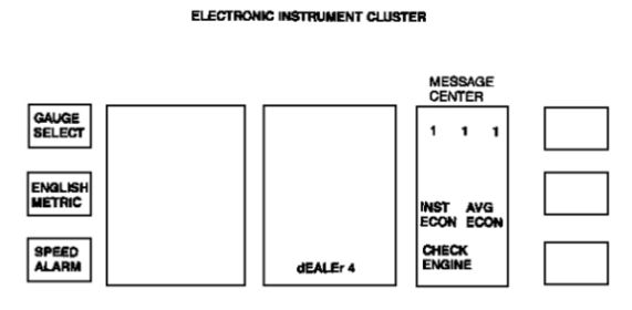
- Figure 11: Electronic Instrument Cluster Center in Self-Test Mode (Continental Only)
- SELF-TEST WITH TRANSMISSION CONTROL INDICATOR LAMP (TCIL)
- The TCIL serves a dual purpose on the 7.3L Diesel vehicle with E40D transmissions.
- The light stays OFF when the Transmission Control Switch (TCS) is toggled once on the instrument panel--indicating the vehicle can attain the overdrive gear position.
- The light stays ON when the Transmission Control Switch (TCS) is toggled again on the instrument panel--indicating the vehicle is prevented from shifting into the overdrive gear position.
- If the light flashes, perform Key On Engine Off Self-Test. The light under this condition serves as a Transmission Malfunction Indicator Lamp. Refer to "Self-Test with Malfunction Indicator Lamp (MIL)" to perform Self-Test.
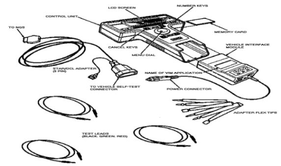
- SELF-TEST WITH NEW GENERATION STAR (NGS) SCAN TOOL
- For a detailed description of the New Generation Star Scan Tool and the variety of tests that can be run, refer to the instruction manual provided with the tool.
- The Diagnostic Test Mode Menu Selection provides access to EEC-IV format on-board Self-Tests. Self-Tests are run using STI and STO lines on the CM. Diagnostic Trouble Code (DTC) definitions are provided if a vehicle has been selected from the Vehicle Entry Menu under Vehicle and Engine Selection menu.
- *For activating Key On Engine Off (KOEO) or Key on Engine Running (KOER) Self-Test
- 1. Connect Self-Test adapter cable to LINK connector of NGS and Data Link Connector (DLC) and Self-Test Input (STI) connector on vehicle.
- 2. Select Diagnostic Test Mode from the main menu.
- 3.Select the desired Self-Test function. Selected Self-Test will be initialized and Self-Test control screen will be displayed.
- 4. Select Slow or Fast coded format with the key selection.
- 5. Pressing the START key will short STI to ground and start Self-Test and DTC acquisition.
- 6. Screen will display DTCs in tabular form with definitions after all fast DTCs are received or as received using slow code format, until all DTCs have been output by the PCM.
- 7.Pressing the STOP key will remove STI to ground and stop acquisition of DTCs. The first received DTC will be highlighted. As you move the highlighting through the DTCs, the definition for the selected DTC will be displayed in the lower box.
- 8. Press CANCEL to terminate Self-Test and to exit to the Diagnostic Test Mode menu.
- 9. Press CANCEL to return to the Main Menu.
- NOTE: Pressing the STOP key (unlatching STI) or CANCEL trigger before all slow DTCs have been output, will erase any Continuous DTCs from PCM memory. Although, if fast code format is used, the DTC will already be displayed with DTC descriptions.
- IF YOU DON'T HAVE ANY OF THESE SPECIALIZED TOOLS.. CLICK HERE
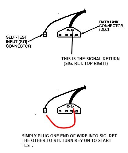
- Use the Malfunction indicator lamp option. This is the only one that I have used. Find your STI connector, mine is under the hood, passenger side, all the way to the back of the engine compartment. It has a black lid that reads "EEC-IV Tester" or "Diagnostic" or something like that, I don't recall exactly. It attaches to the firewall with one of them fancy plastic push-in connectors. Once you find it, the only other thing that you need is a two or three inch piece of wire bared at both ends, connect one to STI the other end to SIG RTN, turn the key to "ON" and you should hear the fuel pump cycle, and the fan should come on briefly. Any fault codes that have been saved will be shown as flashes on your "CHECK ENGINE LIGHT". Count the flashes. You should have three sets of flashes which equals one THREE DIGIT NUMBER. This number is your fault code. If you have read all of the accompanied material, you know that a series of three sets of only one flash (111) is a passing code (no faults).
- TEST EQUIPMENT
- REQUIRED EQUIPMENT
- Self-Test Automatic Readout (STAR), Rotunda No. 007-00004 with cable assembly No. 007-00010. Refer to STAR Tester operation.
- Analog volt-ohmmeter, 0 to 20V DC, (alternate to STAR).
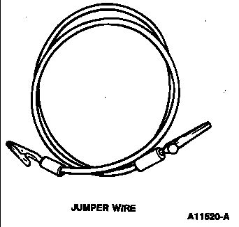
- Jumper wire
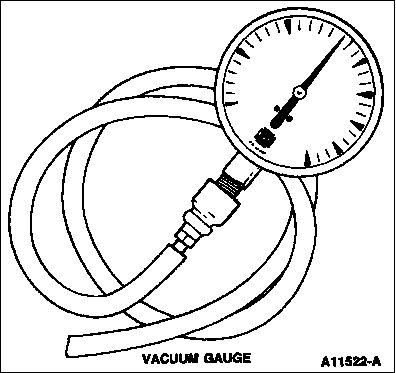
- Vacuum gauge, Rotunda 059-00008 or equivalent. Range 0-30 in-Hg. Resolution 1 in-Hg.
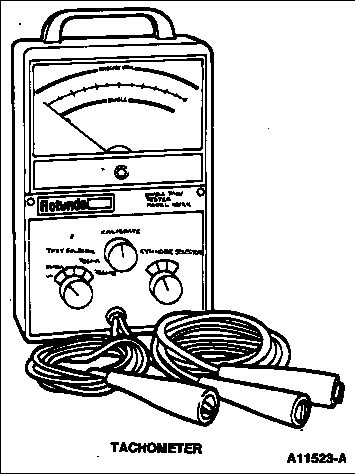
- Tachometer, Rotunda No. 059-00010 or equivalent. Range 0-6,000 rpm. Accuracy ± 40 rpm. Resolution 20 rpm.
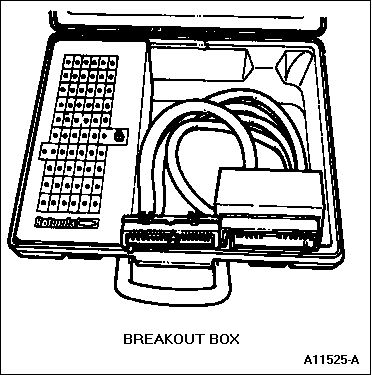
- Breakout Box, Rotunda 014-00322, Special Service Tool T83L-50-EEC-IV or equivalent.
- Vacuum Pump, Rotunda 021-00014 or equivalent. Range 0-30 in-Hg.
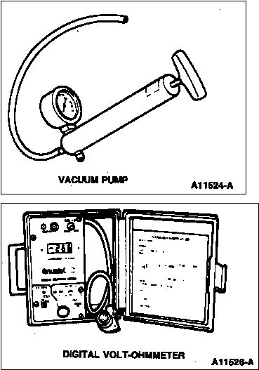
- Digital Volt-Ohmmeter, Rotunda 014-00407 or equivalent. Input impedance 10 Megaohm minimum.
- OPTIONAL EQUIPMENT
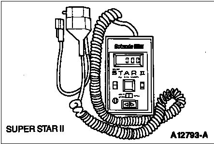
- SUPER Self-Test Automatic Readout II, (SUPER STAR II), Rotunda 007-00028.
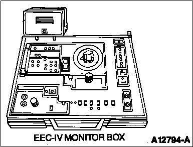
- EEC-IV Monitor Box, Rotunda 007-00018.
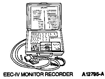
- EEC-IV Monitor Recorder, Rotunda 007-00021.
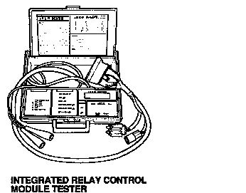
- Integrated Relay Control Module (IRCM) Tester, Rotunda 007-00050.
- New Generation STAR (NGS) Scan Tool, Rotunda 007-00500.
- Electronic Fuel Injection Pressure Gauge EFI/CFI only, Tool T80L-9974-A or equivalent. (Use instructions. For specific applications, refer to Fuel/Engine Service Manual Group.)
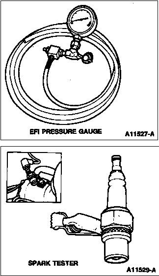
- Spark tester, Tool D81P-6666-A or equivalent.
- Timing light, Rotunda model 059-00006 or equivalent.
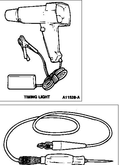
- Non-powered test lamp.