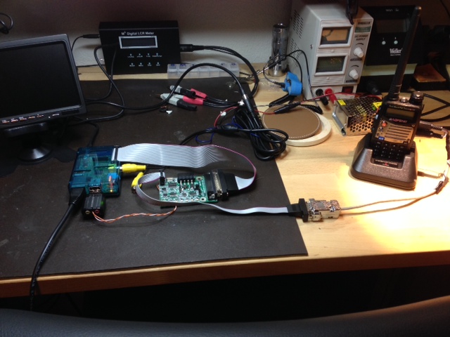
This is a Pi based node using the (modified for 3.3v operation) v3 controller and a BaoFeng UV-5rax+. The whole project was accomplished in an afternoon. I put this page together to add clarity to points I ran into when not using the pre-configured SDcard and building cables for the BaoFeng.
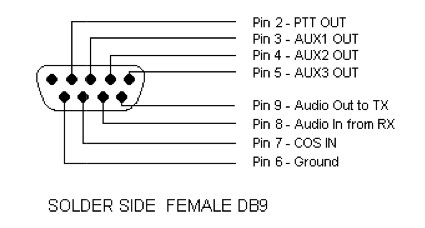
| DB-9 Pin | Function | Lg/Sm Stereo Plug |
|---|---|---|
| 2 | PTT | Shell of Large Stereo of Plug |
| 6 | Gnd | Shell of Sm Stereo Plug |
| 7 | COS | N/A Internal connection Pin 2 |
| 8 | RX Audio | Tip Sm Stereo Plug |
| 9 | TX Audio | Ring of Lg Stereo Plug |
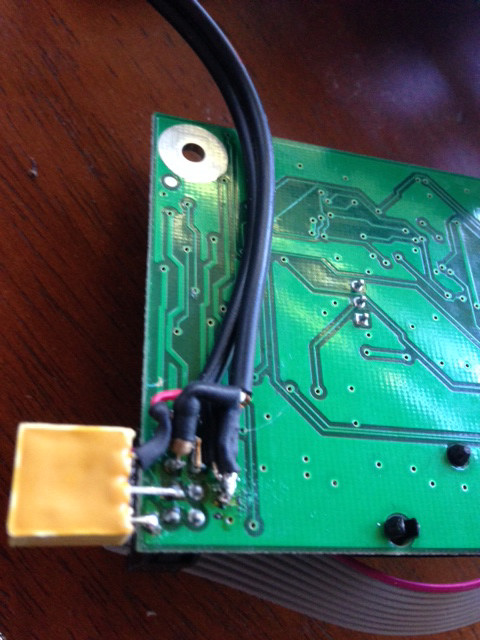
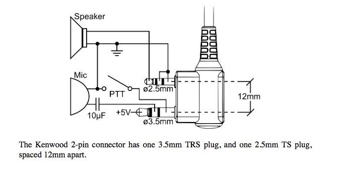
For connections to the radio I used mini (3.5mm) and micro (2.5mm) stereo jacks from RadioShack and picked up the COS signal from inside the handheld.
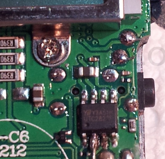
note: pin 2 must be accessed by disassembling the uv-5R. It is found by locating the 8pin SMT chip just below the display and to the right of the printed circle stamped 5R-C6. The second pin in from the left on the lower row is the pin (when the radio is oriented with the antenna port is at the top left). Disassembly Video>
Instructions and setup information are found in the manual. When in doubt read the manual. I built my software stack from scratch, and then did get-irlp-files and the install. There is one ambiguity around the mixer controls that I encountered. "aumixer -L" is in the environment file and rc.mixer file after install, but alsamixer is used on the pi. I changed the environment file to export "alsactl restore" and commented out the export "ausmixer -L". I also changed the rc.mixer file to "alsactl restore" from aumixer -L. PI Setup Manual
I decided to adjust the alsamixer transmit adjustment for best signal to noise ratio which meant that the drive level to the the UV-5R would need to be set another way. I elected to use a 10K trim pot to accomplish this. It is configured as a simple voltage divider. See pics below:
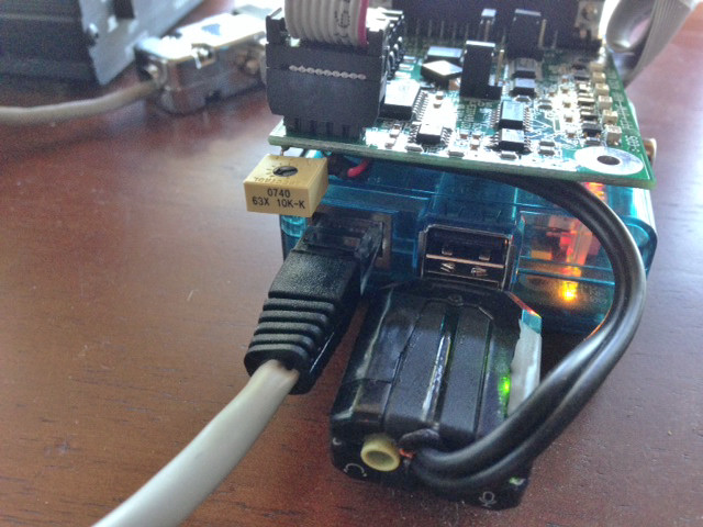
Note that the leads to and from the usb sound fob and the controller card are shielded and short. This eliminated unwanted hum.
Controller jumpers are set to factory defaults indicated by the white slim rectangles beside the pins. Be sure to check as my board was not set to the defaults.
The CW ID needs to be configured in the environment file before it will work. The leading "K" of my CW ID was getting clipped off by some radios, so I uncommented TXDELAY in the environment file.
73, Todd Moore K1TM