I got interested in this project when I read about a December on-the-air activity called the 1929 QSO party in which participants used transmitters whose design and actual tubes were pre-1930. (Specifically, the tube type needed to have been available before 1930.)
There's a lot of romance in this whole thing - the triodes, the simplicity, the breadboard construction, the exposed copper tubing tank coil, and the fact that, even though I've been a ham almost 50 years, this thing would have been an antique even back when I started out.
Finding a tube
Web sources indicated that pre-1930 types are still available at reasonable prices, although some popular triodes have been driven up in price by "audiofools". It was also suggested that one buy some post-1930 triodes for experimentation to avoid blowing up a precious older tube in a design or construction. So when I made my first ever trip to Dayton this year (2010), I was armed with a list of pre- and post- 1930 triodes. Sure enough, the moderate power capable type 45s, popular with audiophiles, were priced at about $45 each -- too rich for my blood. But I did find a couple of type 27s, used but tested, at just $4 each. More my speed. And some more "modern" triodes, 12B4A, 6S4A, 6J5 at about a dollar apiece.
There are a couple of things to realize about this old tube. First is the somewhat unusual filament supply requirements: 2.5 volts at 1.75 amperes. Second, the socket pin pattern is something the precedes the standard octal socket and isn't likely to be in many junk boxes.
Next, a design and the other parts
A search of the web and old literature brought me to a web page by Scott Freeberg, WA9WFA-
http://www.antiquewireless.org/otb/hartley0709.htm
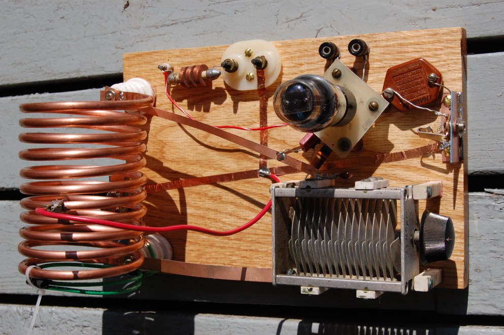
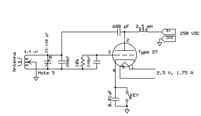
It's a simple design and well described in the article. Count the parts. Excluding the power supply, there are ten components in this transmitter: One tube, five capacitors, one choke, two coils, and one resistor.
I wanted to use "period" parts as much as possible. Note that I have one ancient mica capacitor between the tube and key jack. Another capacitor is a "postage stamp" mica and a third is the most modern -- a dipped silver mica. I opted to use a 1/4 inch key jack and a UHF antenna connector rather than look for Fahnestock clip connectors.
What is it and how does it work? It's actually a VFO (variable frequency oscillator) with output taken from a winding linked to the tank coil. If you're a builder, you naturally start thinking of drift, microphonic effects, and frequency being pulled by changes in the antenna. So yes, expect a "blooper" as these things are sometimes called.
Winding the tank coil
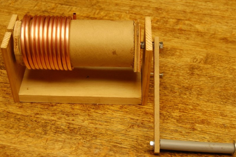
The tank coil has to be the most visually striking part of a TX like this and I could imagine that trying to wind soft copper tubing would be a lot harder than it appears without kinking or flattening the tubing, so I went a little crazy trying to get it right. The tubing is 10 feet of 1/4 inch copper, as found in a refrigerator ice maker tubing kit. In the photo below you can see that I built this winding device. It worked OK even though I did make a few conceptual errors in building it. All's good in the end. It measured about 4.9 uH. My winder used a mailing tube of 3-inch OD. I wound the turns fairly close and sort of expected it to spring apart a little when taken off the form, but it didn't and I spread the turns by hand. One reason is to allow the tap to connect to individual turns. And to fit the output link between turns if desired.

Homebrewing a tube socket (!)
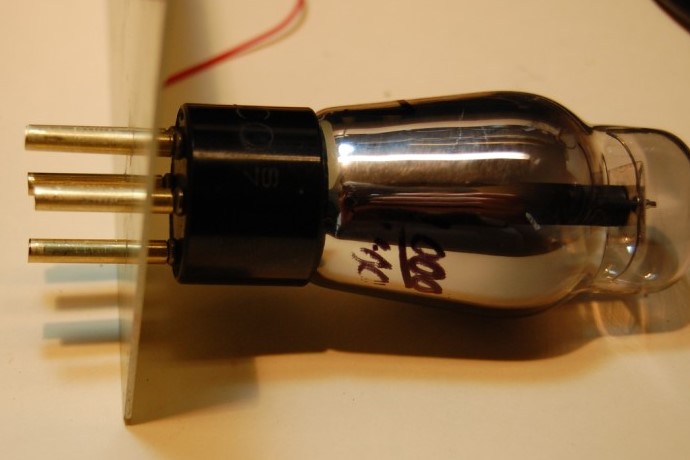
Like I said, the type 27's socket isn't anyone's standard for the past 60 years or so and I didn't have one. I considered wire-wrapping solid wire around the pins but thought a homemade socket would be cooler. I bought some brass tubing from Hobby Lobby, 5/32 OD, 0.014" wall thickness. This gives and ID of about 0.128". I measured the pins at 0.12", so it should be a good fit and it was. Not really snug though, so I thought about flattening the tubes a little for a friction fit. That may have helped, but brass isn't really springy. Anyway, I took some unclad glass circuit board sheet and drilled holes for my sockets and inserted the tube. I think the fact that the pin pattern isn't perfect actually caused some of misalignment forces I wanted to make the pins have firm contact with the sockets. I simply soldered my wires to the ends of the pins with no flattening or preparing "eyes" for wire insertion.

Homebrew tube socket
Other construction notes
I built the transmitter on a piece of solid 3/4 inch oak, 11x7.25 inches. The brackets for the key and coax connectors are made from pieces of circuit board soldered at right angles. Those and my power connector are attached with brass wood screws. The banana plugs and one other terminal are actually threaded into holes tapped into the board. I would have even done that with the B+ if necessary as I think the wood has sufficient insulating qualities. The tank coil stands on beehive insulators that probably aren't really needed for the voltage present, but they look great. The coil insulators and variable capacitor legs are attached with a type of contact cement. I hope it holds. I'll bolt through if it doesn't.
Those flat copper conductors are of two types. The ones elevated off the board are cut from a thin, flexible type of double-sided circuit board material. The strips glued to the board are ground busses and are made from some copper foil for stained glass work I picked up from Hobby Lobby. It works OK I guess, but you want to remove the sticky adhesive from the ends if they're to be soldered.
Power supply
The power supply is beyond the scope of these notes but a couple things are worth mentioning. The high voltage (aka B+ or "plate") supply should be 250 to 300 VDC and capable of 30 to 35 mA. I chose one with fair regulation going from 253 VDC key up to 235 with key down. Fairly steady voltage will minimize the "bloop" or chirp you get while keying. I don't think you could eliminate it though, and remember -- it's part of the charm.
The filament supply is the oddball problem. Standard filament voltages have been 5, 6.3, and 12.6 volts for as long as I can remember, neglecting for the moment the little "pencil" tubes with 1.5 volt heaters. I considered electronic regulation with some kind of slow-start circuit to try to extend tube life. I wound up with something a lot simpler that still gives me that slow start. I used a standard 5 VAC source but put two 0.7 ohm resistors in series with it. To drop 2.5 volts at 1.75 A, you need 2.5/1.75 or 1.43 ohms, so that's close. But the good part is that this scheme gives an inherent slow start feature. That's because the resistance of a filament is much lower cold than when fully heated. With incandescent lighting for example, there's a thing called "tungsten inrush" in which current to the bulb is several times operating current for the first fraction of a second of energization. This probably mechanically and thermally stresses the filament. So anyway, that tendency to initially draw excess current greatly increases the drop in my 1.4 ohm series resistor, slowing down the whole process. It takes four seconds for the filament voltage to reach 2.0 volts and about ten or more to finally get to 2.5.

Schematic of Hartley TX
Testing and a QSO
When I first fired it up into a dummy load everything look fine except, no RF output and no oscillation. It took some thinking before I realized that the load might be preventing oscillation. I had made a link coil from two turns of #12 solid THWN insulated wire sized to fit inside the tank coil and inserted it between two turns. So I removed the load and found that the circuit then oscillated OK. Next I made a "portable" link of two turns connected to the dummy load coax thinking I'd move it in closer and closer until oscillation stopped. Well, I was able to get it right next to the end of the tank coil without causing problems and output power went to 2 to 2.5 watts. Positioning of the coil tap wasn't too critical but I decided on 5 turns out of 11, counting from the grid end. Next I had to fool with the value of the capacitor in parallel with the variable to get the frequency up into the 80 meter band. BTW, I emailed Scott, WA9WFA and he confirmed that you want to get the thing oscillating first, then add the output link.
Although this is a VFO transmitter, adjusting the frequency to a value closer than a few kHz is challenging, even monitoring in a receiver, due to backlash and hand capacity. I may add a small trimmer of 10 pF or so in parallel for fine tuning.
Two watts on 80 meters in daylight in August doesn't spell a lot of random QSOs. So I put out an email to my local club to have someone listen for me and in short order was rewarded with my first QSO with W5RZ, just one town up the road. My signal was chirping away and his rig sounded very fine in my S-40 receiver.
Schematic as PDF file
Back to my ham radio page
Nick, WA5BDU
8/12/2010