The One-Chip Receiver
A 7 MHz CW Receiver Using The
TDA1072 CHIP
This is a project that started as a suggestion from a member of the QRP-L list. The TDA1072 is an AM receiver chip designed mainly to be used in an AM car radio receiver. But it seemed like it would work OK up past the ham HF frequency range and would allow the user to add some sharp IF filtering and find a way to inject a BFO signal so CW (and maybe SSB) could be copied. The idea of using an AM receiver with BFO for CW reception put me in mind of an old Hallicrafters S-40 and many similar receivers. Could I recreate that sound? The project is more of an experiment, a learning experience, and a fun thing to try than an attempt to build a high performance receiver. There are components more suitable than this one when that is the goal.
Some features of the chip-
On board local oscillator. AGC. Output between IF and detector for addition of filtering. Signal strength metering output. The chip has minimal audio drive capability--probably not enough even for sensitive headphones.
Description of circuitry and design choices:
Input matching circuit. The input circuit (components connected to pin 14) is designed to match a 50 ohm antenna input to the 8 k-ohm shunted by 22 pF input impedance of the chip. The circuit is a tank with a capacitive divider at the 50 ohm point. At first, I designed this thing from formulas just to match to the 8 k input resistance. But modeling with the 22 pF internal C showed that resonance was pulled way low. The answer is to adjust either the two capacitors or the tank inductor to restore parallel resonance to 7 MHz. I also started with an 'L' network, but went to this circuit when modeling showed that it offered not only matching but better front end selectivity. The 3.8 uH inductor is wound with 28 turns on a T50-2 toroid.
VFO (Local Oscillator) components: To create your VFO, you just have to come up with a parallel tank circuit connected between pins 12 and 11. But since pin 11 is at RF ground (through the 0.1 uF capacitor), components on that end of the tank can go either to pin 11 or to ground. The 22 ohm resistor in series with the pin 12 side is per the data sheet. The VFO needs to tune a range such that its frequency plus the IF frequency (4.9152 MHz) equals the received frequency. That means we need a range of 2.085 to 2.145 MHz.
OK, how are we going to tune this thing? We QRPers are really liking the benefits of electronic tuning using varactor diodes. I like it a lot due to the mechanical and electrical difficulties of using variable capacitors or inductors. I chose the MV2301 because I have a handful of them. It gives about 90 to 200 pF as tuning voltage goes from 0 to 8 volts. The value of the 10 k pot is not critical; 5 k or 20 k ought to be fine too. The 180 pF capacitor in series with the varactor sets the tuning span. The 10 to 85 pF trimmer sets the lower edge. I'd like about 7000 to 7080 or so. I didn't want the expense of a 10 turn pot, so I need to keep the span low. It's actually a bit too big right now--kind of hard to tune for just the right pitch. Maybe 7010 to 7050 would be better. The tank inductor (12.6 uH) is wound with 47 turns on a T68-2. I used a larger toroid here just to fit all those turns on. Where'd I get the 12.6 uH? Seems like a reactance of tank components around a few hundred ohms is common. This one gives 165 ohms. I might have made it more, but 47 turns is already a lot. It also allows "reasonable" values of tank capacitance.
The VFO works pretty well. Stable and clean enough for casual CW reception with a reasonably sharp filter. You might want to build this part of the circuit first (and power to the chip) and test it. The VFO can be sampled with a counter at pin 10. Don't expect a sine wave there, though. Or just listen to it in your station's receiver.
Power supply: The PS filter consisting of a 22 ohm resistor and 47 uF electrolytic are per the data sheet. I added the 0.1 uF just because. The 78L08 low power 8 volt regulator is to provide a stable supply to the VFO's varactor tuning circuit and is also used for the BFO. Pin 1 also requires supply voltage and is typically fed through the filter's matching transformer as shown. The data sheet specifies 7.5 to 18 VDC for the chip. Obviously, we need to keep voltage high enough for the 78L08 in my receiver--10 to 11 volts is probably the minimum.
IF Filter Section: If you're gonna have a superhet, you might as well have single-signal CW, right? Designing crystal filters is another thing I'm studying these days. I selected the 4.9152 MHz IF partly so I could use these cheap crystals in a filter. A three pole filter isn't going to be super sharp, but it's sharp enough and will give good single-signal reception. The chip puts out the products of the mixing operation on pin 1 for you to filter and expects the filtered results to be piped back in on pin 3. The tricky parts for you, other than coming up with a filter, are matching to the output Z of pin 1 and input Z of pin 3. Which are respectively, 500 k-ohms shunted by 6 pF and 3 k-ohms shunted by 7 pF. Only I had a hard time believing that 500 k-ohm part. Is it really that high? By reverse engineering some of the the example filters in the data sheet, it appears that they were shooting for about 3,500 ohms or so. So I went that way as well. Maybe someone can explain to me what the data sheet is trying to say. The matching transfomer at pin 1 has 13 turns on the primary and 9 on the secondary and is wound on an FT-37-43 ferrite core. The trimmer capacitor is intended to resonate the approximately 66 uH inductance of the primary, which should take around 16 pF.
The crystal filter was designed for 1675 ohms input and output Z. I ended up with that weird value after several design iterations and would probably choose something more sensible if I were starting over. On the pin 3 end, I originally was using an L matching network to transform 1675 ohms to 3,000. But I was plagued for the longest time with tremendous QRM from SW BC AM stations around 7.49 MHz. I finally decided that the 47 uH molded choke I was using might be picking up the signal, so I replaced the L network with a 1600 ohm resistor. It helped a lot. I may have lost 3 dB of gain, but it was well worth it.
I initially experimented with the receiver using no IF filter at all. That's OK just to see if any sound comes out, but you will get a LOT of sound if you're making a 40 meter receiver due to the proximity of strong AM broadcast stations. You need some kind of IF filter for sure.
Audio Section: The audio filter at pin 6 consisting of the 0.01 uF, 3300 pF and 12 k-ohm components is per the data sheet. You could change it for a lower roll-off frequency for CW, but it's not really sharp enough to worry with anyway. OK. The data sheet says the chip puts out 130 mV of audio with a 50 uV input signal. That's not a lot. A normal audio line level is 0.5 to 2 volts. So this chip probably can't even drive sensitive headphones to reasonable levels without some amplification. Also, with the 3 k internal and 12 k external resistors, you have a source resistance of 15 k-ohms, which is fairly high. I did all my initial testing by plugging in a set of powered computer speakers to the audio output. That worked fairly well, but the need for more gain is indicated when signals are weak. I plan to add an internal LM386 audio amplifier. (See addendum at the end of this page.) Meanwhile, the 15 k source resistance was bugging me so I decided to transform it down. I did this with an FET source follower. I chose this method because it seemed like a fun thing to do and anyway I'd been reading Wes Hayward's paper on FET biasing and thought I'd try it. http://www.qrp.pops.net/ has it. You could probably leave this stage out without ill effects, but you'll still want some audio amplification which is what I'm going to add next. The FET stage doesn't amplify the voltage level; it just gives a lower source impedance. Use any old cheap N-channel JFET if you build this stage. (I did finally verify that the FET stage can drive efficient headphones to audible levels with reasonably strong signals. But more gain is still needed.)
Beat Frequency Oscillator (BFO): You need this if you plan to receive CW or SSB. This circuit is a crystal and/or transistor test circuit I took from Solid State Design for the Radio Amateur. You want to inject the BFO frequency about 600 to 800 Hz higher than the center of your filter's passband. The passband is usually a bit higher than the frequency stamped on the crystals--mine is around 4.1960 MHz. I was initially trying to get the BFO on frequency by tuning a series capacitor, then finally realized that this is a parallel mode oscillator and put the trimmer in parallel. I spent a lot of unnecessary time worrying about how and where I'd tie in the BFO signal. It turned out that I just needed a couple inches of wire as an antenna or gimmick capacitor if you prefer, routed to a point near pin 3. It turns out that you can have too much or not enough injection, so you have to experiment with the wire's position while listening. As a future improvement, I'll probably rig up a pot and voltage divider, connect the thing up directly, and be able to vary the injection in a more predictable fashion.
Miscellaneous other connections: Pin 4 is the other side of the post-filter input and is RF grounded through the 0.1 uF cap, since the filter is single ended (one side grounded). The cap on pin 5 is per the data sheet. Those on pins 7 and 8 are also--these are for AGC time characteristics and you could experiment with them if you wanted to. The connection to pin 10 is the oscillator output for testing or counting. I left the R value off the schematic--it's 2.2 k-ohms.
The S-meter connection is from pin 9. I haven't actually hooked one up, but it would be fun to have one--a little visual appeal. If you use an analog milliameter as shown, it should be 1 ma full scale. If you just want to check signal strength with a voltmeter across the 2.7 k resistor, it will be about 20 mV for no signal and 2.8 volts for an extremely strong signal.
Pin 2 is the "standby" control line. Be sure to ground it to enable the receiver. This may a good place to mute the receiver during transmit if you use it with a transmitter.
Troubles: I had a lot of the usual problems not worth mentioning, so I won't. But the biggest problem that is worth mentioning was AM SW BCI (AM Shortwave Broadcast Interference). There are some extremely powerful broadcast stations located just above the 40 meter amateur band. It's hard to build a front end filter steep enough to keep them out. The receiver worked fine in the day time, when propagation did not favor these stations. But at night, the bombast and missionary fervor of these guys drove me nuts. I tried several things. Put the board into a box, with grounding of the boards at a single point. I had actually been having trouble with longwave interference too--a local station on 610 kHz. The box cured that, but it didn't cure the shorwave stuff. If fact, putting the lid on made it worse. Trying to make a long story short now, I finally began to suspect that a molded choke was picking up these signals. So I replaced the L network between the crystal filter and pin 3 with the 1.6 k resistor you see now. That helped a great deal. I still hear the SW BC a little, but not much. Now I'm eyeing that 1 mH choke in the BFO circuit and thinking of replacing it with a bifilar toroidal choke.
Success! After I nearly abandoned the thing in disgust, I'm now proud to say that it's not a bad little receiver. It could use a bit more sensitivity, but I think that's in the audio stage, as I mentioned before. I'm going to pair it with a suitable transmitter--QRP homebrew TX or maybe a 60's vintage novice transmitter, and make a few QSOs.
Some reference info:
The data sheet for the TDA1072 is pretty easy to find. I found it here TDA 1072 A data, from Philips If you can't find it, I'll email it to you. By the way, I don't know what difference the 'A' suffix makes.
AM chips don't seem too common these days. But I've learned that many FM single chip receivers are also adaptable for use in CW & SSB service. There's an article in the current (11/2002) issue (#9) of the New Jersey QRP Homebrewer that discusses this. It's by Harold Smith, KE6TI.
Any questions or comments--email me at kennnick@gmail.com
Would I recommend this chip and circuit for someone wanting to build a
simple receiver?
Not really, unless your interest is AM broadcast or shortwave. If I undertake another single chip receiver, I’ll be using one of those FM radio chips which many have used with great success for SSB and CW, such as the MC3362, MC13135 or MC13136. For examples, see:
http://www.qsl.net/vu2upx/Projects/hfrx_mc3362.htm
Or The SIMPLEceiver in QST, September 1986.
Here's the schematic. Thanks to Zim, VK3GJZ for fixing it to fit most screens while still retaining detail:
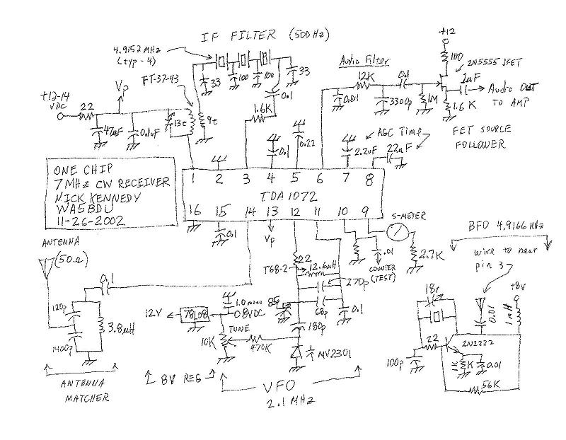
Alternate schematic - Chuck Carpenter W5USJ took the ugly one above and drafted it nicely for me in this GIF. VIEW
And finally, a couple pictures of the thing ...
Here's the can I put it in, for what it's worth. It's a Snickers Christmas candy box, with Norman Rockwell painting on the lid. On the left is the tune control, then the +12V power connection, then the antenna input via BNC, and on the right is the audio output to the powered speakers.
And here it is with the lid off. This is after I seismic tested it twice by dropping it on the floor and knocking all the boards cockeyed. I sat the boards on insulating spacers and hot glued them down. The main board is in the center, with the chip in the center of it. I put the crystal filter on a separate board in the rear. (Way bigger than it needs to be.) The antenna matching network was originally on the main board on the right side of the chip, but I wanted to get it well away from pin 3 to help deal with the SW BCI, so I moved it to a separate board on the left and made the connections via coax instead of plain wire. (The white stuff is coax.) And when I got around to building the BFO, I hadn't left enough room and had to put it on the separate board on the right, currently knocked askew. The only ground connection to the board is via the coax shield.
Yeah, you'd think a one chip receiver would be compact rather than huge like this. What's the sense of a minimalist receiver if you're going to use a quarter acre of circuit board? Just remember, this is a prototype. With some good foresight, you should be able to jam the whole thing onto a much smaller single board.
73--Nick, WA5BDU
Addendum 1: Additional audio stage sufficient to drive a speaker.
I tried a couple of things to give me some more audio. First, I added a single transistor amplifier after the FET follower with a gain of about 6. That was fine to give me enough push to drive my powered speakers to full loudness, but not sufficient to go it alone. So I finally got around to adding the LM386 audio amp which is described below. (It doesn't need a lot of description, since this is one of the most popular and easy to use chips out there.)
There are a few versions of the LM386. The -1 version is lower powered and has a lower supply voltage rating. I didn't want to have to regulate down to 9V or 6V and didn't want the VFO to have to share its regulator, so I went with the -4 version. It's maximum supply voltage is 18 VDC, so it ought to be reasonably happy with a 12 / 13.8 volt supply. The data sheet gives several simple example circuits. I adapted the one called "AM Radio Power Amplifier", appropriately enough. I just made a couple changes to constrain the frequency response toward the CW range a bit. I increased the size of the cap at pin 2 from 2200 pF to 0.015 uF for more roll-off on the high side and decreased the output coupling cap from 250 uF to 100 uF for more low frequency roll-off. The other changes were based on parts on hand. I didn't have the ferrite bead called for in the output filter, so I just used an FT-37-43 with five or six turns.
There are several "good practice" things in this amp to improve stability and frequency response that you might wish to leave out in a minimalist version. One is the 10K resistor and capacitor at pin 2. The other is the ferrite bead, 47 ohm resistor, and 0.05 uF cap on the output. I elected to go the conservative route and put them all in. Experiment if you wish. I used a 30K audio pot because that's what I had. Values from 5K to 50K ought to work. As another stability enhancing measure, the data sheet said to twist the power supply leads together tightly. I didn't want to fool with twisting a couple of enamel wires, so I used two conductors of a ribbon cable and ran them through an FT-37-43 a few times to aid in blocking RF from the supply leads.
Results? Wow, this thing is blasting me now. Plenty of audio and then some. It really helps a lot in my overall perception of the receiver. Right now I'm listing on 40 in the day time, with a 3 foot diameter loop antenna hanging from the ceiling right behind my chair. This antenna obviously puts a whole lot less signal into the receiver than my outdoor dipole, yet I'm hearing lots of stations with plenty of audio.
I do still have the extra transistor amplifier in the chain, but like I said, that's almost too much. You can increase the gain of the LM386 by putting a resistor and capacitor in series between pins 1 and 8. See the data sheet or my drawing. I'm sure you could have satisfactory results in a simpler configuration that eliminates the FET follower too. Just make the 0.1 uF coupling capacitor coming out of the filter a lot larger--100 uF of so. And do make the volume control pot 20 K or so, due to the large audio output impedance of the chip plus filter.
Addendum 2: The BFO.
I finally got around to reading the voltage on the signal strength pin. It was 1.75 VDC with no signal and not much more than that with a strong signal being received. That indicates a strong signal and sort of confirms my idea that the AGC is not audio derived--it's reacting to the BFO alone.. The problem with this reading is that it means that the AGC is running the receiver gain way back even when no signal is being received. So I moved my gimmick capacitor (wire) a lot further away from the post-IF input until the strength dropped way down. I still seemed at that point to have plenty of BFO injection for strong signals and perhaps my overall sensitivity has increased. So you may want to experiment in this fashion in your circuit. And maybe a pot or trimmer controlling the injection level would be better than this crazy method I'm using.
Here's the audio amplifier circuit:
NRK 12/13/2002