Steve
Weber, KD1JV wrote a very nice controller program for the NJQRP AD9850
and AD9851 based DDS synthesizer boards, called the DDS-30 and DDS-60.
He also posted his source code for other programmers to tinker
with. I decided to play with it for a couple of reasons.
First, I wanted an entry point for attempting to learn
programming the ATmel AVR series microcontrollers, and second, I'm
going to make my DDS-60 board the LO (VFO) for my receiver project, at
least initially, and I wanted some more features.
The program as written is already pretty sophisticated, offering RIT, XIT, user programmable IF offset and band selection. Plus a nice keyer. I've added two things -
1) The ability to use a rotary encoder in parallel with the existing joystick tuning control. This allows use of a conventional (if misnamed) "analog knob" for frequency control.
2) The ability to control both the DDS-30 and the DDS-60 from the same firmware. Surely everyone has both boards(?)
To implement item #2, I've added another menu choice which will display the chip number that you can toggle to. For example if you are currently in the DDS-60 (AD9851) mode, the menu choice will be "AD9850". This is a persistent selection, so you don't have to make the choice every time you power up the Butterfly. Its starting screen now reminds you which mode you are in by displaying the number of the chip it assumes it is controlling.
Also along with item #2, there are now EEPROM storage locations for reference oscillator frequency informaiton and IF offset information for both board types, so you can configure them independently.
To the lower right of the Butterfly is a 4-pin connector for the rotary encoder. It is wired to J402, which is the second connector from the left below the LCD. The mechanical encoder just needs three pins (A, B and GND), while the optical encoder adds +5 VDC to power the optical sensors. In the front with the black knob is a mechanical encoder temporarily wire-wrapped to the board for testing.
Left of the proto board is my homebrewed optical encoder. The wheel and sensor came from a bathroom scales. Note that the bushings for the 1/4 inch shaft were made from 1/4 inch phone jacks.
The optical encoder has the advantage of more steps per turn. Also, the mechanical encoder has detents and moves with a click for each step. Not exactly a good choice for an "analog feel" knob. But really it does pretty well for general usage and it's obviously much more compact.
Instructions and hardware connections
Rotary encoder
This feature functions in parallel with the joystick UP/DOWN controls, so either may be used. Another connector was added to the board to accommodate the encoder. The connector to be used is J402. Looking at the top of the board, in the lower left corner is a group of 10 holes where you installed the connector that goes to the DDS board. That’s the J400 (PORTB) connector. Just to the right of it is another 10 holes for J402 (PORTF / JTAG). This connector would normally be used for JTAG programming. If you are programming via the built-in bootloader and serial port as described by Steve in his documentation, you aren’t using JTAG.
Here's Port F from the top - of J402, that is,
10 8 6 4 2
9 7 5 3 1
Pin 1 = Encoder Input A
Pin 5 = Encoder Input B
Pin 4 = Vcc (+5 volts)
Pin 2 = Ground
Don’t worry too much about input A versus B confusion. If your encoder tunes the wrong way, just swap two wires at the most convenient spot.
There are no specific operating instructions for this feature. Hook it up and go.
AD9850 / AD9851 selection
If you have both a DDS-30 and DDS-60 board, this feature will allow you to control either with the same software. In the existing menu structure, the less frequently used choices are accessed by continuing to hold the joystick to the left for several seconds after the BAND menu choice appears. A new choice appears at the end of these lesser used choices, so continue to hold left until it appears.
The menu will show the chip type that you will be changing to. So if you are currently in the DDS-60 (AD9851) mode, it will show AD9850 as your choice, and vice-versa for the DDS-30 mode. When you see the choice, release the joystick. Similar to the other choices, you may now press Joystick IN to make the change, or Joystick RIGHT to cancel the menu.
Your choice is saved to eeprom, so when you start up the butterfly, it initializes in the last used mode. As a reminder, it initially displays current mode AD9850 or AD9851 on the LCD on startup.
Separate eeprom memory areas are used for reference frequency calibration information, so you can do the REF CAL for each of your boards and the saved information will be used for the appropriate board. Separate eeprom memory is also used for the IF offset frequency, so you can have different offsets, or an offset for one but no offset for the other.
Technical issues
Since the DDS-30 is considered usable to 30 MHz, the 6 meter band setting won’t be useful for that board. Also if an IF offset is used; note that it is added to the operating frequency. So if you have a 10.7 MHz IF and intend to operate above 19.3 MHz, the DDS-30 will again be above its recommended range.
What's a Butterfly?
It's a demo or prototyping board from ATmel. It features their ATMega169 microcontroller plus some nice stuff like an LCD display, serial port with a built in bootloader program, 5-position mini-joystick, a speaker, and the usual array of goodies you find in a modern MCU including timers, digital inputs and outputs, ADC, PWM and probably XYZ. The MCU has about a zillion pins, but many are taken up by the fairly complex LCD module. There are still plenty to play with though. The LCD gives you six alpha-numeric digits plus some misc symbols you could use as flags.
ATmel provides a big and sophisticated integrated development environment (IDE) with editor, assembler, debugger and other fun stuff. Even if you don't write programs, you can use it to "burn" or program hex files by others into the MCU.
The Butterfly sells for about $19 to $25 from places like Mouser, Digi-Key and places that sell MCU stuff to developers and hobbyists.
Credits & references
First of course thanks to Steve Weber for writing this excellent program and making the source code available. And I haven’t even discussed the included keyer! You’ll find additional source code from Steve and other programs for the AVR Butterfly here, and lots of great radio projects and products …
http://kd1jv.qrpradio.com/
Butterfly pins alternate uses, PDF file
This file by Joe Pardue was very useful in selecting pins for the encoder. Find it via the AVR Freaks web site or
http://www.smileymicros.com/
NJQRP DDS-60 & DDS-30 boards
Great QRP site with lots of projects & technical info …
http://www.njqrp.org/
Source code
I used this exercise in programming to learn a little about how to program the AVR 8-bit MCUs in assembler and a little about the Butterfly. I added a lot of comments to Steve’s code and commented my own additions pretty heavily, so they might be useful to anyone who wants to extend things further. To clear up some accidental version number confusion ... this is my "internal" version 3 source and hex code, but it's the first version I released to the world. So it starts up saying it's version 1. Don't worry, you got the latest. Thanks Dan in the UK for bringing that to my attention.
You can get the files from me or from my web site here:
Source Code
Hex code
This is what you need to load into your Butterfly board to run the firmware -
Firmware HEX file
73—Nick Kennedy, WA5BDU
kennnick@gmail.com
Return to WA5BDU ham radio page
The program as written is already pretty sophisticated, offering RIT, XIT, user programmable IF offset and band selection. Plus a nice keyer. I've added two things -
1) The ability to use a rotary encoder in parallel with the existing joystick tuning control. This allows use of a conventional (if misnamed) "analog knob" for frequency control.
2) The ability to control both the DDS-30 and the DDS-60 from the same firmware. Surely everyone has both boards(?)
To implement item #2, I've added another menu choice which will display the chip number that you can toggle to. For example if you are currently in the DDS-60 (AD9851) mode, the menu choice will be "AD9850". This is a persistent selection, so you don't have to make the choice every time you power up the Butterfly. Its starting screen now reminds you which mode you are in by displaying the number of the chip it assumes it is controlling.
Also along with item #2, there are now EEPROM storage locations for reference oscillator frequency informaiton and IF offset information for both board types, so you can configure them independently.
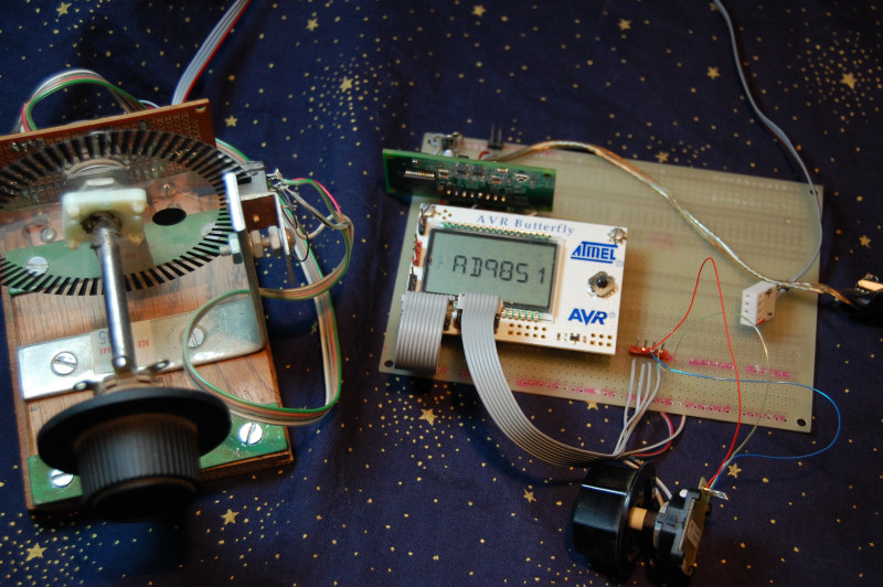
Here's
a picture of the hardware. I mounted the AVR Butterfly board and
a socket for the DDS on a proto board. The DDS-60 is installed
vertically above the Butterfly.
To the lower right of the Butterfly is a 4-pin connector for the rotary encoder. It is wired to J402, which is the second connector from the left below the LCD. The mechanical encoder just needs three pins (A, B and GND), while the optical encoder adds +5 VDC to power the optical sensors. In the front with the black knob is a mechanical encoder temporarily wire-wrapped to the board for testing.
Left of the proto board is my homebrewed optical encoder. The wheel and sensor came from a bathroom scales. Note that the bushings for the 1/4 inch shaft were made from 1/4 inch phone jacks.
The optical encoder has the advantage of more steps per turn. Also, the mechanical encoder has detents and moves with a click for each step. Not exactly a good choice for an "analog feel" knob. But really it does pretty well for general usage and it's obviously much more compact.
Rotary encoder
This feature functions in parallel with the joystick UP/DOWN controls, so either may be used. Another connector was added to the board to accommodate the encoder. The connector to be used is J402. Looking at the top of the board, in the lower left corner is a group of 10 holes where you installed the connector that goes to the DDS board. That’s the J400 (PORTB) connector. Just to the right of it is another 10 holes for J402 (PORTF / JTAG). This connector would normally be used for JTAG programming. If you are programming via the built-in bootloader and serial port as described by Steve in his documentation, you aren’t using JTAG.
Here's Port F from the top - of J402, that is,
10 8 6 4 2
9 7 5 3 1
Pin 1 = Encoder Input A
Pin 5 = Encoder Input B
Pin 4 = Vcc (+5 volts)
Pin 2 = Ground
Don’t worry too much about input A versus B confusion. If your encoder tunes the wrong way, just swap two wires at the most convenient spot.
There are no specific operating instructions for this feature. Hook it up and go.
AD9850 / AD9851 selection
If you have both a DDS-30 and DDS-60 board, this feature will allow you to control either with the same software. In the existing menu structure, the less frequently used choices are accessed by continuing to hold the joystick to the left for several seconds after the BAND menu choice appears. A new choice appears at the end of these lesser used choices, so continue to hold left until it appears.
The menu will show the chip type that you will be changing to. So if you are currently in the DDS-60 (AD9851) mode, it will show AD9850 as your choice, and vice-versa for the DDS-30 mode. When you see the choice, release the joystick. Similar to the other choices, you may now press Joystick IN to make the change, or Joystick RIGHT to cancel the menu.
Your choice is saved to eeprom, so when you start up the butterfly, it initializes in the last used mode. As a reminder, it initially displays current mode AD9850 or AD9851 on the LCD on startup.
Separate eeprom memory areas are used for reference frequency calibration information, so you can do the REF CAL for each of your boards and the saved information will be used for the appropriate board. Separate eeprom memory is also used for the IF offset frequency, so you can have different offsets, or an offset for one but no offset for the other.
Technical issues
Since the DDS-30 is considered usable to 30 MHz, the 6 meter band setting won’t be useful for that board. Also if an IF offset is used; note that it is added to the operating frequency. So if you have a 10.7 MHz IF and intend to operate above 19.3 MHz, the DDS-30 will again be above its recommended range.
What's a Butterfly?
It's a demo or prototyping board from ATmel. It features their ATMega169 microcontroller plus some nice stuff like an LCD display, serial port with a built in bootloader program, 5-position mini-joystick, a speaker, and the usual array of goodies you find in a modern MCU including timers, digital inputs and outputs, ADC, PWM and probably XYZ. The MCU has about a zillion pins, but many are taken up by the fairly complex LCD module. There are still plenty to play with though. The LCD gives you six alpha-numeric digits plus some misc symbols you could use as flags.
ATmel provides a big and sophisticated integrated development environment (IDE) with editor, assembler, debugger and other fun stuff. Even if you don't write programs, you can use it to "burn" or program hex files by others into the MCU.
The Butterfly sells for about $19 to $25 from places like Mouser, Digi-Key and places that sell MCU stuff to developers and hobbyists.
Credits & references
First of course thanks to Steve Weber for writing this excellent program and making the source code available. And I haven’t even discussed the included keyer! You’ll find additional source code from Steve and other programs for the AVR Butterfly here, and lots of great radio projects and products …
http://kd1jv.qrpradio.com/
Butterfly pins alternate uses, PDF file
This file by Joe Pardue was very useful in selecting pins for the encoder. Find it via the AVR Freaks web site or
http://www.smileymicros.com/
NJQRP DDS-60 & DDS-30 boards
Great QRP site with lots of projects & technical info …
http://www.njqrp.org/
Source code
I used this exercise in programming to learn a little about how to program the AVR 8-bit MCUs in assembler and a little about the Butterfly. I added a lot of comments to Steve’s code and commented my own additions pretty heavily, so they might be useful to anyone who wants to extend things further. To clear up some accidental version number confusion ... this is my "internal" version 3 source and hex code, but it's the first version I released to the world. So it starts up saying it's version 1. Don't worry, you got the latest. Thanks Dan in the UK for bringing that to my attention.
You can get the files from me or from my web site here:
Source Code
Hex code
This is what you need to load into your Butterfly board to run the firmware -
Firmware HEX file
73—Nick Kennedy, WA5BDU
kennnick@gmail.com
Return to WA5BDU ham radio page