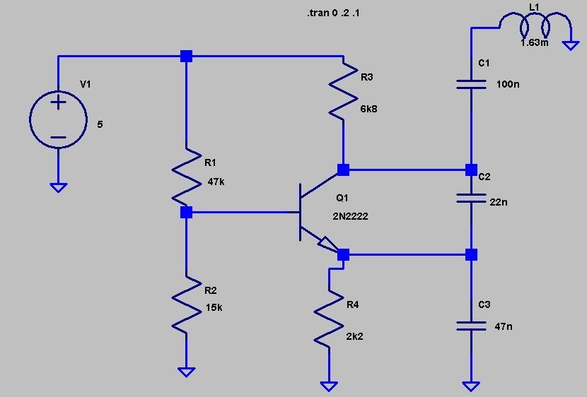
This circuit was in EDN's
"design ideas" section in the March 5, 2007 issue. It's a fairly
simple circuit and an easy way to investigate how the inductance of a
toroid (or any core) is changed by saturation, which in this case is
caused by applying a current to a secondary winding. With this
circuit, the oscillator frequency is a function of the controlling
current and so it can be used to measure current without direct ohmic
connection to the circuit.

This schematic was produced by LTSpice.

This schematic was produced by LTSpice.
I originally used 16 turns
on an FT37-43 toroid for about 100uH, but it wouldn't oscillate until I
increased supply voltage from 5 to about 12 volts, and applying the
measurement current would stop oscillation. The frequency was
over 150kHz. I did a new coil using a slightly larger FT37-43 with 50+
turns to give 1.63mH. I wound four turns onto the toroid for the
measurement winding. Frequency would move around (rise) after each
adjustment, either due to some time constant or because current was
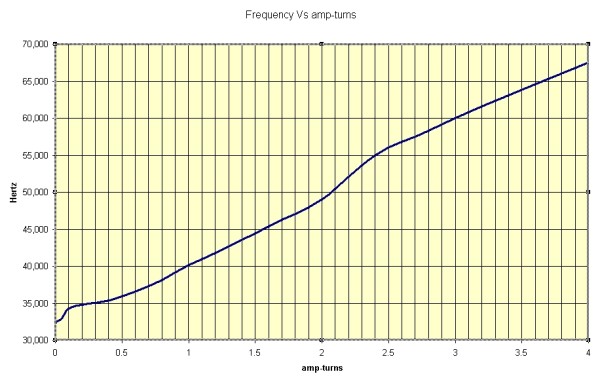
changing below the 0.4 A-t level. (100mA on the meter times four
turns.) Supply voltage was 5.07 VDC. In some cases it seems to do
better with higher supply voltage.
The article hinted that this technique wouldn't be repeatable enough for an accurate current measurement technique. That's probably true. For order-of-magnitude measurements or detection of overcurrent, it would be fine. It could also be used in a feedback loop (PLL) to control frequency using current and inductance as opposed to the traditional varactor method.
This measurement could also be used to infer the inductance (and permeability) changes with current. In my example, 4 ampere-turns approximately doubled the frequency. Since frequency is proportional to the square root of inductance, the inductance was reduced by a factor of four (4).
I also experimented with bringing a fairly powerful magnet close to the toroid and was able to move the frequency up to 200 kHz with it.
The graph below shows how frequency changed with amp-turns through the core
