"EFHW" - the end-fed half wave antenna
Introduction
One of the cautions you sometimes see in discussions of the end-fed antenna are "avoid multiples of a half wave." The very valid reason for this is that the high impedance of the feedpoint was outside the range of most transmitters and external tuning units.
In the past few years however, this exact configuration has been used to advantage and its popularity has increased among hams, especially the QRP subculture. The fact is, if a proper matching network is provided the antenna can be a good performer with several advantages.
· "No feed line" antenna
· Low ground losses mean only the simplest grounds or counterpoises are needed
· Works well in vertical, sloping, inverted vee, and inverted L configurations
· The matching network is simple to construct and use
· Can also use on harmonicaly related bands, such as 40 and 20 meters
All of these things point to the EFHW as an ideal temporary antenna for the hiker or camper. Ease of installation appeals especially to me because of my long life of sorrows trying to get lines through trees. I don't have a pitcher's arm and I've proven to be fairly inept with various slingshots and other antenna raising contrivances. Amazingly enough, just one good shot over a 20 foot limb can be all it takes to put up a quite functional 40 meter EFHW in an inverted vee configuration.
Technical details on matching
The feedpoint impedance of an EFHW isn't the easiest thing to nail down, other than to say it's probably a few thousand ohms. It will vary somewhat with wire size and more with variations in configuration. A value of 3,000 ohms is a good estimate. The popular way to provide a match is to simply design a toroidal transformer with a turns ratio of about SQRT (3000/50). Using a single winding with a tap is common, but separate windings may also be used. OK. But usually the reactance of the high side windings is not large compared with the antenna's 3,000 resistance and so the magnetizing inductance tends to shunt the load. This problem is corrected by adding a variable capacitor in parallel with the winding to raise its impedance by parallel resonating it. So now we have a transformer plus tuning capacitor which will be adjusted to resonance as indicated by the lowest SWR on the transmitter side. It's common to build a simple SWR indicator into the tuning unit's enclosure.
Below are photos of my "conventional" EFHW tuner with SWR indicator
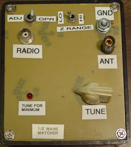
It's in a box that's 4.25 x 5 inches, sort of big for the intended application of carrying on hikes. But it could be cut down to size with a little care. Note that I chose to switch between two secondary taps, so my turns ratios are 32:6 (LO) and 32:4 (HI) for matching 1,400 or 3,200 ohms to 50 ohms. I used a combination banana jack / binding post for the antenna and a binding post only for the ground. The top panel is cut from a piece of single sided circuit board, and the components are mounted / soldered to the other side as you see in the photo below.
My 50-ohm resistors are each two 100 ohm resistors in parallel. The SWR circuit's toroid hangs from the resistor on the right.
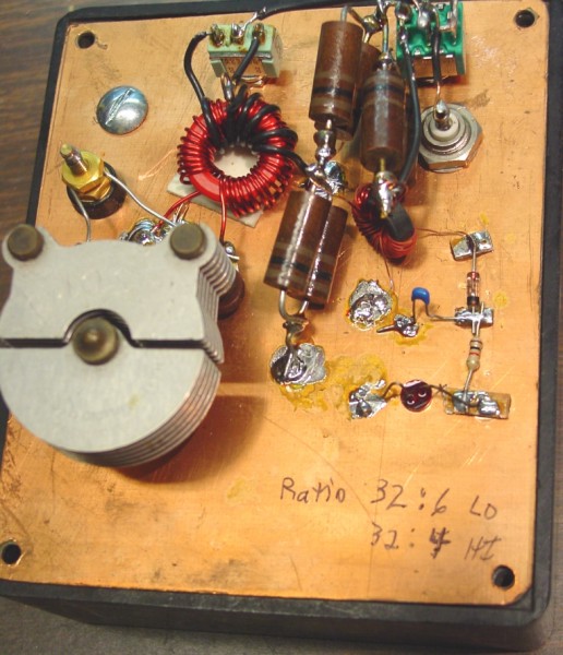
This is the inside view of the tuner. A simple version would include just the variable capacitor and large red toroid transformer. The switch to the left of the toroid is for LO/HI impedance antenna. The big resistors and other components at the top are the SWR indicator. The capacitoris 50pF and the toroid is a T130-2 core with 32 turns on the primary, giving 11.3uH. The secondary is 6 turns tapped at 4 turns for the high/low selection.
The schematic for the EFHW tuner is shown below:
Will my EFHW matcher give me a 1:1 SWR?
One thing about the EFHW tuner is that it's a fixed ratio transformer, so it
might not be able achieve 1:1 (50 ohm match) with all half wave wires.
For example, if my half wave wire happens to have 3,000 ohms feedpoint resistance look at my possibilities. My
transformation ratios are (32/4)^2 or 64 and (32/6)^2
or 28.4.
In the LO position I'd transform to 105 ohms and have a 2:1 SWR. In the
HI position, I'd transform to 3000/64 or 46.9 ohms, giving me a 1.06 SWR.
But that's idealistic since I chose the ratio based on an assumed 3,000
ohms.
Suppose the feedpoint resistance is actually 2500
ohms. Then my two possible transformed values are 88 ohms for a 1.76 SWR
and 39 ohms for a 1.3 SWR. Not bad, but you're not going to get to 1:1
with this configuration.
Then the other issue is reactance, which will exist if your antenna
significantly deviates from 1/2 wave. The circuit doesn't have a specific
means of cancelling reactance, although maybe tuning the resonating cap
off-resonance a little might do it to a certain extent.
Some hams think SWR is a measure of how well an antenna "works". In other words, an antenna with a 1:1 SWR works better than one with a 1.6:1 SWR. That's not necessarily so. But if you have a 1:1 SWR fetish, this system might not be for you.
With those caveats given, I tune for minimum brilliance on the LED, get on the air, and make QSOs. After all that though, I checked with a meter and my 66 ft, 5 inch piece of #24 AWG Teflon insulated wire over a tree did give 1:1 SWR with my switch in the HI Z position.
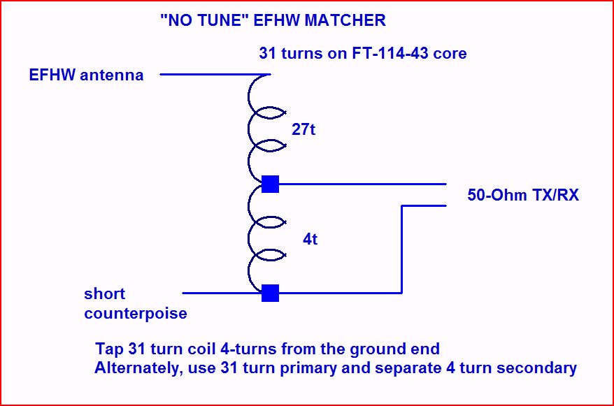
"No-Tune" EFHW
Tuner
It occurred to me that if the toroid could be made with enough reactance in the primary winding to be large with respect to the antenna resistance, the resonating capacitor wouldn't be needed. To get that much inductance would take a ferrite core for its high permeability. I used a FT-114-43 core and with something over 30 turns I could get 580uH to 700uH, giving at least 25,000 ohms on my lowest band of interest (40 meters). So I gave it a shot and it worked pretty well, resulting in a one component matcher. Below is a photo of the assembled matcher:
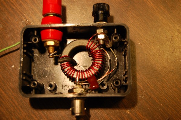
This photo shows the latest version, using magnet wire and a tap for the secondary.
I have 31 turns tapped at 4 turns from ground. With separate windings, ground isolation was possible but I got better results with a common. That's the bus wire running form the (black) ground binding post to the shell of the BNC connector. The tap point connects to the BNC's pin. The high Z side of the overall winding goes to the red antenna post and the other to the ground post. Not much need for a schematic, eh?
Here's an update from a post to the 4SQRP email list describing how I measured losses in this matcher:
I have a
homebrew log power meter built from a Kanga parts kit (AD8307 chip) based on an
article by Hayward and Larkin in the June 2001 QST. I wound a second
transformer identical to the one in my matcher and connected the two high
impedance windings together. My MFJ259B signal source goes to one 50 ohm
winding and the other goes to the power meter. Reference power readings
were made with the MFJ259B direct to the power meter. The difference
between the two, divided by two, is the loss in one matcher. Here are the
results -
40M 0.8 dB
30M 1 dB
20M 1.3 dB
15M 2.2 dB
I use mine on 40, 30 and 20 and don't consider these losses excessive.
Update June 2012
After
getting an email from a guy having a little trouble with this matcher, I went
back and made some SWR measurements. Not quite as good as I remembered,
maybe. I reworked the thing twice. First by
winding a less sloppy secondary winding. That didn't do much so I
tried winding the core with #22AWG enamel (magnet) wire and tapping it 4-turns
from the ground end instead of having a separate winding. (The photo shows this
version.) Not sure if that helped my SWR. Readings while using a
4.7k resistor as a load are given below. As you can see, this tuner
should be considered for 80 through 20 meters. For higher bands, try 15
turns primary and 2 secondary and see how that works.
BAND SWR
80 1.4
40 1.3
30 1.3
20 1.7
17 2.4
15 3.2
Sorry, but still more measurements and changes below ...
Also, some didn't agree that no diagram was necessary. So here's one:
More updates! I ran into some issues when measuring SWR with my real EFHW
as opposed to the 4k7 ohm resistor. The 20M SWR was too high. (The real world
tends to do that to you.)
I think the biggest issue is that I typically use my 40M EFHW on 40M and 20M,
so on 20M it's really an End Fed Full Wave. It's
given great on-the-air results, so I never worried about SWR much.
My first thought was to parallel the input side of the toroid with a capacitor
to cancel magnetizing reactance. I didn't have much luck with that while
using the 40M EFHW on both bands. So I put up a separate 20M EFHW
(33'-3" long) for testing on that band. I found that putting 220pf
in parallel with the input (TX side) brought my 20M SWR down to 1.6. With
the same capacitor still installed, I got a 1.3 SWR on 40M using the 40M EFHW.
So now I'm happy with it as a "no-tune" matcher for 40M and 20M and
I'm sure 30M would be OK. I haven't looked at higher bands.
There are three variables that will interact. One is, just how long is an
EFHW supposed to be? Do you use the 468/F formula, or something else?
Another is where to place the tap on the coil? Is 4k7 ohms a good
estimate for calculating it? (My antenna wire is #22 Teflon insulated.
Smaller wire equals higher feed point resistance.) Thirdly comes the value of the parallel capacitor, if used.
Here are some EFHW references and resources:
http://www.njqrp.org/n2cxantennas/halfer/index.html Discussion by Joe Everhart, N2CX on the NJQRP page
(Sorry, the link was dead so I removed it. Try a Google search.) Bill Jones, KD7S in the Adventure Radio Society Archives describes his "film can transmatch", which is a matcher for the EFHW.
(Oops, dead link again. But I did want to leave the reference & description) Richard Fisher, KI6SN, also in the ARS Sojourner, describes the SWR indicator I used in my conventional tuner, with credits to N7VE and W6JJV. The circuit is nice because it uses an LED instead of a meter and also because it is a dissipative bridge--assuring that SWR won't exceed 2:1 when in the Tune mode.
http://www.w8ji.com/2end-fed_1_2_wave_matching_system_end%20feed.htmSome detailed technical analysis and matching circuits by Tom Rauch W8JI
http://www.aa5tb.com/efha.html Steve Yates, AA5TB on the EFHW. Steve is one of the major EFHW advocates and has a good page.
January 21, 2007, January 20, 2008, May 6, 2008, June 25, 2012, January 12, 2015
Nick Kennedy, WA5BDU