by Nick, WA5BDU
I
like my little lightweight MFJ-4225MV power supply. It puts out
about 25 A, maybe 20 continuous, which is enough for my IC-706GII or my
new K3. I also liked the fact that the fan was fairly quiet.
But that was in comparison with my FT-1000 with its fairly
noisy fan and my hamshack computer with two or more attention getting
fans. After upgrading to a new laptop and the quietly cooled K3,
the MFJ P/S became the distracting source of white noise in the ham
shack. Actually, this project ought to be applicable to any P/S
that can run with the fan off in low load conditions.
Goals:
I don’t like noisy fans. I also don’t like noisy fans that start, run for a few seconds, and stop again. If the unit is hot enough to require a fan, I want it to run long enough to cool the sink down a little.
I don’t think the fan is too critical in this P/S, so I decided to go with a temperature reached after 5 minutes at 20 amps load. In this way, it might never come on during light duty operation and just listening. If it does come on, I want a deadband of about 10 degrees at the heat sink before it goes off. If the 20 A load continues, the fan might never go off, which would be OK.
Preliminary measurements:
First I made some temperature measurements. The P/S has two heat sinks, one with two devices mounted to it and one with just one. Using a LM34Z sensor glued to the heat sink with two devices, I measured the temperature at 20 A load for 10 minutes. It went from 74.5 F to 115 F at 5 minutes and 132 F at 10 minutes. But then I realized the sink toward the middle of the unit was getting hotter. So I moved the sensor there and did the test again. Ambient was 79F. In 5 minutes T was 134 F, in 10 it was 138 F.
I also experimented with running the fan at lower voltage. It got very quiet at less than 11 volts, but with the cover back on, it was not so quiet. Pulling air through the perforated cover made the difference. The fan current was 127 mA at 14.9 V and reduced to 80.6 mA at 10 volts. So a 2N7000 with a rating of 200 mA could handle it.
Design:
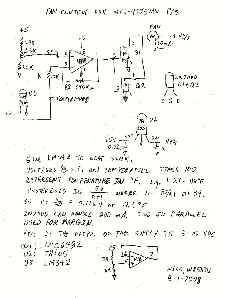
I was going to use a comparator (LM319A), but couldn’t find where I'd stowed them in my vast component collection. My next choice was an op-amp that could be driven rail to rail and work on a single 5 V supply. For a chip with saturation voltage (high) of 5V and low saturation voltage of 0V, the hysteresis is 5 / (N + 1) where N is the ratio of the feedback resistor to the input resistor. I used 390 k and 10 k for a hysteresis of about 5/40 or 0.125 volts, 12.5 degrees F. The op-amp of choice was a LMC6482. It's SMT, but an easy to handle S08 size. I used a little adapter board to interface it to the non-SMT components. The chip has two op-amps, so I biased the unused one to Vcc/2 to keep it from doing anything crazy.
The LM34Z temperature sensor is kind of over-kill for this application, but it made calculating settings easy. Its output is directly proportional to temperature, so volts * 100 = temperature in degrees F. I considered using a Vbe multiplier as a sensor but already had the LM34Z in hand from my temperature measurements. To maintain a constant deadband, the op-amp’s supply voltage needs to be constant, so I used a 78L05 regulator. The LM34Z will work off 5 volts, so I connect it to that bus. You could also run it off the power supply's output voltage.
Since the fan’s current draw is low, the 2N7000 works as a switch. One could handle the current OK, but I put two in parallel for conservatism. The fan goes in the return (to ground) lead. I cut the black wire to the fan and connected the end from the fan to the drains of the MOSFETs. The other end of the black wire is ground and goes to the board for its ground. I shaved the insulation from the intact red wire and tapped off another wire to go to the board’s 78L05 regulator’s Vp/s input.
Load test –
I adjusted the setpoint to 131F (1.31 volts) with the trim pot.
From loading to 20A to fan ON: 2 min, 5 sec, I kept it loaded one more minute, then removed the load
Time for fan to go off after unloading: 1 min, 12 sec
In a CW QSO test at 100 watts, I made a couple of typical transmissions with no fan, but it ran during my third turn at the key.
Schematic of fan control circuit (GIF format):

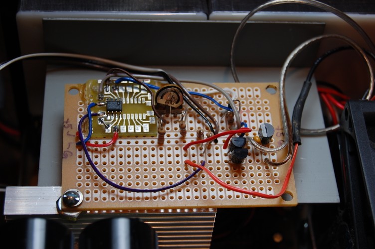
Photo of fan control board mounted in P/S

LM34A sensor glued to heat sink


Top
left is the adapter board for the SMT op-amp, setpoint pot right of it.
At far right is the 78L05 regulator and the two devices crowded
together are the 2N7000 MOSFETs. I like to use the Radio Shack
prototype board for one-of-a-kind projects like this. I tapped
the heat sink for a 4-40 screw and used a large nut for a spacer or
stand-off (lower left corner of board)
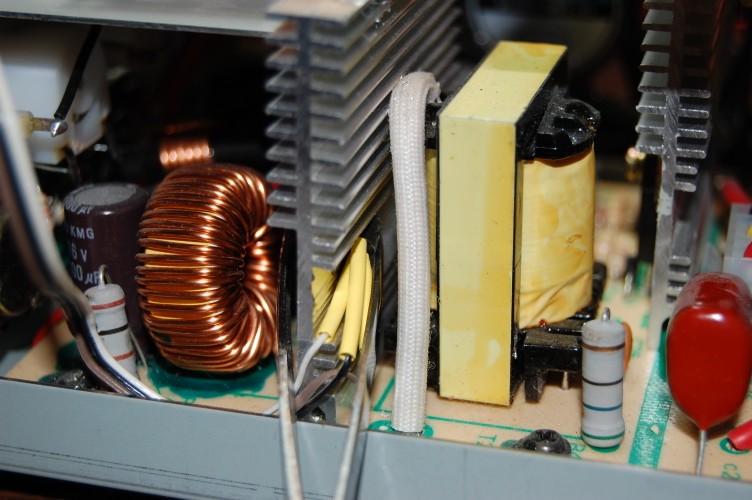
LM34A sensor glued to heat sink

The
LM34Z temperature sensor is a TO92 device. I soldered on leads
and insulated them with the yellow tubing pushed all the way up to the
body. I glued the sensor to the heat sink. Sticking out of
the power supply are the two prongs of a set of tweezers clamping the
sensor in place while the glue dries. Hope it holds.
Some kind of mechanical clamping arrangement might be better.