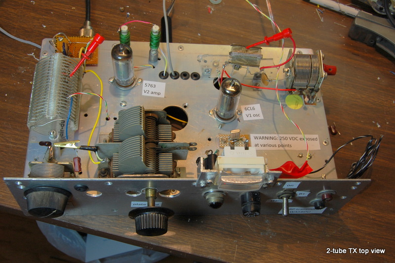
When you play with 5 V and 12 V solid state circuits almost exclusively, you may lack an appreciation for the danger associated with working with 250 volts, or even 120 volts, either of which can be lethal. This is not a DIY article, it's a discussion of design choices and observations in building a tube-type transmitter, not intended for duplication. Hams who are not experienced in building tube equipment should become well familiar with safety practices before attempting such projects.
Now on with the show-
I'd only built one tube transmitter before, but it was from a Handbook circuit. I wanted to do a QRP transmitter of my own design, more or less, and this is the result. My goal was to have 5 watts or so out, CW only, crystal controlled.
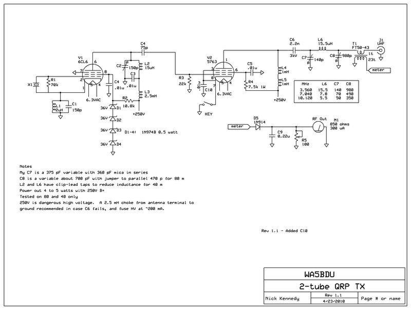
Another goal was to be able to use a miniature HC-49/U crystal in a tube oscillator. Will that work? Some say tube oscillators have too much crystal current for these crystals. My research said that a tritet oscillator has low crystal current, so I settled on figure 8, page 249 of Orr’s The Radio Handbook (1959), substituting a 6CL6 for the 6AG7. It sort of complicates things - there's a tuned tank output so one more thing to adjust. That's part of the fun though, right? And there's a parallel tuned circuit in series with the crystal tuned 20% or so above the crystal frequency. How do you work multi-band operation with that thing? BTW - find the Bill Orr book and lots of other vintage tube technology books here -
http://www.pmillett.com/tecnical_books_online.htm
Let's show the schematic before further discussion ...

Resistance at pi-net input:
There are plenty of calculators for doing a pi-network, but I need to know what resistance to convert the 50 ohm load to. I think for class-A it’s a matter of a simple load line, but I’m not sure about class C. Can I use the same formula we use for class C transistor finals, which is Z = Vcc^2 / 2*Po, or supply voltage squared divided by twice power output?
XC1 = 240 ohms, XL = 265 ohms, XC2 = 36 ohms. Using these values and a formula for computing Rin from C1 and C2 (QST 1/84 page 48) in my spreadsheet, these values indicate that R at the tube side is 3360 ohms.
Glen Leinweber VE3DNL goes along with the rough formula V^2 / 2Po and thinks a pi-net would with Q of 15 would just about keep things legal. Dan Tayloe also thinks the same formula would be used.
Tank in series with crystal-
RFC to shunt feed the final-
I needed another RF choke and was low on pi-wound chokes. Came up with a couple 1 mH small ones and a big 2.5 mH. I hate to waste one that’s big enough for a 100 watt or bigger rig on this rig, but 1 mH only gives about 22,000 ohms on 80 meters, which is only 4 or 5 times the plate load resistance, a little marginal. I decided to use both 1 mH chokes in series. They’re nice in that they have a 6‑32 stud for mounting on a panel.
Plate current or relative power metering-I initially wired the B+ through a miniature lamp rated 12 volts at about 60 mA, so I assume I’m only dropping 5 volts or so at 40 mA or less. But I noticed that using the plate current indication lamp on the tube TX wasn’t effective at all in tuning for maximum output power. There was not a good sharp dip. So I decided to try measuring the output current at the antenna jack and tuning for maximum antenna current. I initially wanted to have that drive an LED and tune for maximum brightness, but I found that LEDs go from dim too bright to abruptly so I used a meter. The circuit is shown on the schematic and there's some more discussion on my blog entry-
http://wa5bdu.blogspot.com/2010/04/rf-output-current-meter-for-qrp-tx.html
Backwave?
I noticed that the TX was keying my RF-sensed antennas switch when not transmitting. With key up I measure 20 mW out. So there’s only 23 dB of difference. Not sure how this happens. Maybe capacitively coupled from grid to plate of the amplifier tube? I don’t see it as a big problem. I added a B+ switch so I can put the TX in standby with the filaments still on. I have to be able to do that anyway when I go to receive since my oscillator runs continuously.
About voltage and power
About building tube rigs-
Wow, it's a major pain in the neck, ain't it? Mounting just about any component is an adventure in mechanical engineering. For lots of hams with skills in this area, I know that can be lots of fun and the final product can be really nice to look at. But for me, if it weren't for Manhattan, Ugly, Wire Wrap and Proto Board methods, I'd probably never get anything built.
How does it work?Looks pretty good. I figured if the HC49/U crystal was being over driven it would let me know either by failing completely or by chirping excessively. But I don't seem to have much if any chirp, so I'm calling it success. I've only had it on 80 and 40, so despite the schematic, this is a two band rig.
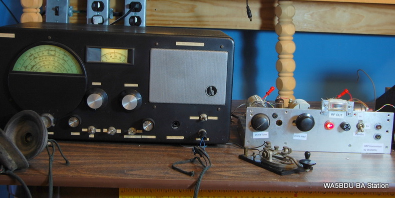
I've had two QSOs so far, matching the TX perfectly with a Hallicrafters S40A receiver.

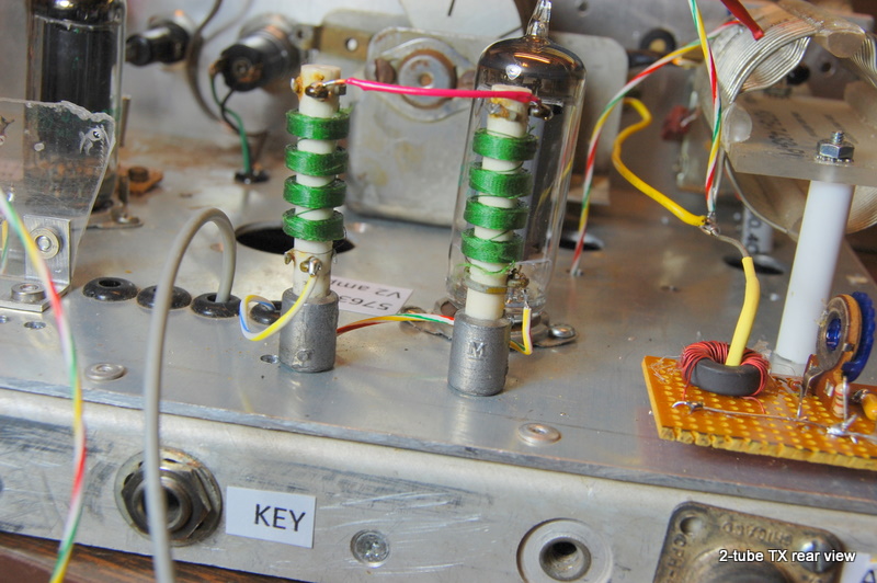
And just because I love the looks of those pi-wound chokes, here's a picture of the rear of the rig. Don't they look like futuristic hi-rise apartment buildings, as in The Jetsons? Also shows the RF current metering board with the antenna output lead passing through the toroid.

There you have it -
Nick, WA5BDU
A couple of updates:
1) I was very pleased to have my little transmitter described in CQ magazine's QRP column, written by Cam, N6GA. It's in the April, 2011 issue.
Cam also came up with a neat power supply circuit (should be in the June issue) that uses something I didn't know existed -- a little LR8 3-terminal TO92 regulator (the size of a 78L05) that can handle 450 volts on the input side. He follows it with a TIP50 pass transistor to get his 250V.
2) I received an interesting email concerning my transmitter from David Newkirk, W9VES. David has a lot more experience and knowledge in the area of tube transmitter design than I do and offered his suggestions and comments which I reproduce below. I haven't had time to try them yet, but plan to. Meanwhile anyone want to follow along the lines of my design might want to consider the ideas below.
From the email by David Newkirk, W9VES:
_________________
So that's all pretty interesting. Especially, I think, that you can measure grid current in that way. My understand is that RF grid current only occurs on one half cycle, or close to it, so it has a DC level. It's blocked by the coupling capacitor and so the DC return path is through R3, where David would add the 100 ohm resistor with which to make the measurement.
Back to WA5BDU page