The following battery discussion is reproduced with permission. It is written by:
C. L.
"Red" Scholefield
|
First, let's define "fast charge". The industry standard is any charge rate that will charge the cells in 1 hour or less.
This fast charge capability thing is very interesting. Almost all ni-cds manufactured today for R/C systems can accept fast charge (up to C rate, that's the rate at which you can charge the cells in approximately one hour). Cells that are specifically sold as fast chargeable go through another step in the process. This step involves charging a sample from the production lot and then measuring the end of charge voltage. Cells with the highest end of charge voltage are then analyzed for internal pressure. If the internal pressure is acceptable, that is not above a preset limit, the whole production lot is "blessed" as being fast chargeable. Of course this adds a finite amount of cost to the cell as they must be "formed" prior to being ship in order to be fast chargeable.
Cells not destined for fast charge applications are shipped "unformed" by some manufacturers. Forming the cell is the process of the first charge after it is assembled. Nothing more nothing less. When you charge your R/C system packs for the first time you are "forming" them. This is why you see the instructions telling you to charge the packs for 16 to 24 hours before you first use the system. Some manufacturers ship all their cells in the formed condition as part of their manufacturing process.
So in most instances you are safe fast charging the R/C packs (transmitter or receiver) on the market if you first make sure they get a good first cycle formation charge - 24 hours at the slow rate. Where the problems arise is that some of the fast charge systems available are a little sloppy when it comes to terminating the fast charge, or they are pushing the cells too hard (higher than the C rate charge) and then damage occurs. As a rule of thumb if you packs are not getting hot (slightly warm is OK) you are not damaging them in the fast charge process. When pushing too much current into cells not designed to accept it there is the risk of driving the cells above 1.6 volts (the hydrogen over voltage point) and electrolyzing the water in the electrolyte and generating hydrogen. This is a cumulative event and repeated fast charge at these rates will result in sufficient accumulation of hydrogen to cause the cells to vent. When they do vent there is a chance that the chemical balance will be disturbed and the cell capacity will fade. Understand that the pack may not be fully charged when the fast charge terminates. It is a good practice, if you are going to fast charge frequently, to top off the packs using the slow charger. This will bring all cells to the same state of charge and "balance" the pack. Otherwise the cell that is not fully charged will be the limiting cell on the next discharge. This continues until there is a major unbalance in the pack and one cell can be driven into reverse (if you don't crash first).
While volumes have been written on this subject I would like to relate it to the specific application of R/C , separating fact from fiction and enabling the R/C fraternity to focus on more serious issues of the day, like convincing your wife it's too foggy to clean the pool so you're going flying while the field is not so crowded.
The primary failure mode of Ni-Cd cells (outside of user abuse) is separator deterioration. This will occur in all Ni-Cd batteries as they age. The separator breaks down allowing the plates (electrodes) to touch and short out the battery. Millions of testing hours on thousands of cells has established the mean time to failure of a single cell to be 8 years for cells/batteries maintained at 25C (77F). Higher temperatures will significantly reduce these numbers. Mean time to failure means the time that it takes for half the cells in a given population to fail. As the cells are built into packs the mean time to failure decreases. For a 4 cell receiver pack the mean time to failure comes out to be 5.7 years while an 8 cell transmitter pack falls to 4.8 years. Now it is completely possible that the average R/C modeler doesn't want to tempt statistics to the point where half of his battery packs should have failed. A more reasonable number would be the expected time for 0.1% of his batteries to fail. The number comes out to 58 weeks for a receiver pack and 49 weeks for a transmitter pack. For the more adventurous willing to live with 1 failure in a hundred, he can stretch his receiver pack to 103 weeks and his transmitter to 87 weeks. Does this mean that he should rush out and buy new packs at these intervals? Not really. Proper battery monitoring, while it may not significantly increase life, will give you ample warning that your pack should be considered for replacement. Remember, normal failure is the deterioration of the separator system. As the separator deteriorates (oxidizes) self discharge rate of the battery increases significantly. A pack that looses 15% or more capacity over a week of open circuit stand is at risk. A pack that looses 10% overnight should be used for ballast only. Check your pack with a cycler or some technique that gives you the amount of capacity available immediately after discharge and then (after fully charging again) after a rest period of 5 to 7 days.(NO, this isn't MEMORY!). Doing this at least quarterly (if you are fortunate enough to live where you have a flying season longer than 3 months) will greatly increase your odds of crashing by some other defect than battery failure.
The number of cycles you put on your battery is secondary in the life equation, again, assuming you don't abuse them by high rate over charge, vibration or exposure to high temperature. I know of very few people that totally exhaust their battery packs while flying (at least not as a matter of course) so the packs seldom see a full discharge and the risk of cell reversal is nil. Test have demonstrated that hundreds of cycles of reversal where 140% of the rated capacity is taken out in a driven discharge resulted in a capacity loss that was barely measurable. Many multi speed power tools use the technique of tapping the battery for speed control with no adverse effects on the battery. A single cell can be discharged through a load to zero volts without damage. In fact this is a good way to determine if a cell has suffered from separator deterioration. A cell discharged to zero volts will recover to over 1 volt open circuit if left to stand. Those that will not are approaching the steep part of the failure curve and could be a crash waiting to happen. Bottom line: the number of full charge/discharge cycles that can be accumulated by today's Ni-Cd technology is in the 400 to 500 cycle range. Of course partial discharges seen in the R/C application can extend the use cycles to significantly more than this. It doesn't take a battery expert to figure out the amount of flying time you can accumulate on 500 full discharges. We are talking in excess of 1000 hours. If you put in a full two hours a week in the air every week year round, you would be well into the next century before you reached 500 cycles. Separator failure or old age will probably do you in before you run up 500 cycles. Meticulously recording the number of discharge cycles to establish a replacement schedule can be a study in futility and should be left to the electric R/C indoor microfilm pylon set. Don't worry about reversal. If you have left your switch on overnight or for even a couple of days, just give the pack a good long slow charge using your regular charger supplied with the system for 48 hours and you will probably be OK. It would be prudent to run a capacity check cycle after such an incident just to make sure.
Long term overcharge, leaving your packs plugged in to the charger supplied with the system, while considered an acceptable practice for many consumer applications can contribute to a reduction in battery life. First, as a battery goes into overcharge, oxygen is generated on the positive electrode and then recombined on the negative electrode. This oxygen rich atmosphere only accelerates the oxidation of the separator. As the oxygen is recombined on the negative it generates heat.We all know how to make a chemical reaction speed up, turn up the heat.
One further phenomena recently brought to light after years of testing is that of cadmium migration. This is a transfer of cadmium metal through the porous separator structure to form a conductive bridge between the electrodes. In simple terms a high resistance short which causes the cell to self discharge, shunts charging current to where the cell takes longer to charge and ultimately, if left of continue, become a hard short which, if happens during a period when batteries are part of, or contributing to the direction of an airborne operation, result in a rapid depletion of model resources. The same testing reference also confirms that the same amount of charge put into the battery in a short period significantly reduces the cadmium migration. Therefore using a simple appliance timer to switch your charger on for about an hour a day minimizes the overcharge and yet maintains the packs at peak charge should an airborne operation be called for at any time. For the experimenter, a charger designed to charge the battery at C rate (1 hour rate) run at a 10 to one duty cycle (on 0.1 second, off 1 second) is more effective than charging continuously at the C/10 (10 hour rate common to most system chargers) and will enhance battery life. For a maintenance charge a 25 to 1 duty cycle is recommended. This pulse charge is better than even a very low trickle charge for maintaining the battery as cadmium migration is driven by passing current through the separator (charging) over a period of time. The rate of cadmium migration does not seem to increase proportionally to the current density, leaving us with the conclusion that getting the job done (replacing charge loss through inherent self discharge) quickly by a pulse of charge current is better than dragging it out with a long sustained overcharge. While this gives battery a break it will probably give rise to a new generation of exotic (expensive) chargers focusing on the dreaded cadmium migration phenomena (hereafter referred to as CMP, people only take three letter problems seriously) and leave the dreaded memory effect (DME) alone for awhile. Just remember that you can do the same thing with a $5.00 timer and spend the savings on a subscription to your favorite R/C magazine, RCM.
Storing the battery is no big deal. Living in Florida where there are no cool (damp, dark, moldy) basement work shops, I store my batteries in the refrigerator on off flying season (July 3rd 9:30 AM to July 4th 7:00 AM). Those living in Northern climates don't really have anything to worry about (there must be some advantage) but should remember about the trunks of cars and what happens to batteries you leave them in there when you are visiting us for a winter flying vacation.
Looking at the battery voltage after several months of storage is an excellent way to pick out a weak cell (use straight pins to probe each cell). If a cell voltage after several months drops noticeably below any of the others, beware. You have a potential problem and the pack should be relegated to some benign surface application. While we are on the subject of measuring battery voltage, consider getting one of the little digital voltmeters available through electronic hobby outlets. They give you a precise reading and are well worth the modest investment. Second piece of advice. don't listen to the R/C car guys when it comes to batteries, they have never experienced the thrill of real rip roaring, crank shaft bending, dirt in the transmitter, kind of crash and as a consequence take liberties with batteries that would make Leclanche and Volta turn over in their graves to say nothing about causing me just a little heart burn when they get me cornered in "technical" conversations.
One of the failure modes in Ni-Cd cells is shorting. While many things can contribute to shorting one of the significant contributors is cadmium migration through the separator where it forms a conductive bridge, ultimately shorting the cell
Cadmium migration is a function of the time the charge current is flowing through the battery and less a function of the level of current. Therefore we have found that high pulses of charge current to maintain the charge state are better than a steady low rate (trickle) current. This is very difficult to quantify as their are many other factors contributing to the life equation but improvements in battery life of 10 to 20 percent by pulse charging vs trickle are not unrealistic.
Therefore we have found the sustaining a pack at the fully charged state by way of pulsing the charge is better than an continuous trickle charge.
Some charges employ this technique. You can do the essentially the same thing rather simply and at a very low cost.
Simply connect your regular wall module charger that came with your system to an appliance timer. Intermatic makes a good unit for around $5.00. Set the trigger pins on the timer so that it is on for 1 hour a day. When you return from a flying session turn the timer wheel so that the on off triggers come up in 14 to 16 hours. Then turn the timer knob to on. This will give your pack a full charge and then a sustaining charge for 1 hour a day. The battery can be left in this manner for a long time between flights and still be maintained at a fully charged state with minimal overcharge.
If you only fly a couple of flights, you can just set the timer so that you get 6 or 8 hrs before you go into the 1 hr.day mode. If we assume a normal 2 hr flight time for a system and you only fly 20 minutes. Then the charge you need to return is 20/120 times 16 hours, or about 3 hours.
It is good to know what your system consumes in the way of energy per minute of flight. This can be determined by first charging a pack and then discharging it on a cycler to determine how much capacity it has - fully charged. Then recharge and go fly. Record your system on time and immediately discharge the pack when you return home. This will tell you how much capacity you have left. Lets say you fly for 40 minutes and when you discharge the pack you get 390 mAh. From your initial discharge from a fully charge pack you got 585 mAh. This would mean that you discharged 195 mAh in the 40 minutes you flew or about 5 mAh/min. From this you would know that your pack is good for 116 minutes of flight time.
The system usage will vary, depending on your flying style, size of the plane and number of servos used.
"How should I store my batteries at the end of the season? What should I do to them when I put them back in operation?"
The batteries should be removed from the transmitter and plane for longer term storage. Here in the south where a lot of us work out of our garage work shops I recommend putting them in the refrigerator (not the frezzer) during the off season. While not so important where your workshop rarely gets above 23 degrees C (74 F) the refrigerator is still a good bet. Why? The failure mode of Ni-Cds is separator failure, this is the material that keeps the plates from touching each other. When it fails the cell shorts. At higher temperatures it oxidizes faster. In fact, the rate doubles for every 10 degrees C increase.
"Should I store my batteries charged or discharged?" It doesn't really matter, they will self discharge in a few months stored at room temperature. If you are going to store them in the refrigerator the charge will remain for a lot longer so I would discharge them first to 4.4 volts and them put them away. Good cells will just set there in the discharged condition (the voltage can vary considerably but is usually above 1 volt). In a battery with damaged "worn out" separator in the cells, the cells are apt to short if left in a discharged condition. This is actually good since it is the first indication of a cell that's going bad and it is best to replace the pack. A battery left on trickle charge will seldom short out since it is in the charged condition and any short that tries to develop will be zapped by the charge in the cell. Partial shorts (those having fairly high resistance) can be developing that can cause the cells to self discharge at a higher rate than normal and possibly leave you short in the middle of a flight after you just measured the cell when it came off charge with your ESV and everything looked OK.
The reason I recommend removing the batteries from the transmitter and plane is to protect against "black wire" disease. Should a cell short while in storage there is a high probability that there will be some leakage that can lead ultimately to the "black wire" problem.
Now when your batteries are coming out of storage, before charging, check the voltage without a load on the battery. It should read well over 4.0 volts even if it has not been charged all winter. They should be essentially fully discharged, flat as we say in the business. In this condition if the battery is going bad it will probably have shorted and you will read zero volts on that cell. It may be a soft short, one that could be blown away merely by the simple action of slow charging. Don't do it! It is just lying there waiting to bite you. Replace the pack. Cut out the "good" cells if you want and use them in something less critical than your model. If you have access to a cycler running though a couple of charge/discharge cycles is a good idea just to make sure you are getting the capacity you are suppose to. Anything less than 80% of rated is suspect. Once at the field, pre-flight battery checks are in order, particularly at the beginning of the season. Since those that religiously check their flight packs with an expanded scale volt meter seem to crash less (due to battery failure) one must assume that the ritual is smiled upon by the R/C Gods.
The use of redundant parallel fight packs (packs may be of different capacity but MUST be
of an equal number of cells) is an excellent way to increase the available flight time and
significantly improve the reliability of the on power system. The simplest means is to run
two complete wiring harness, switches and charge jacks from each pack and plug one into
the normal battery port and the other into an extra channel on the receiver. No diodes or
isolation is required (see below). This is simpler and more reliable than some of the
complex battery backup systems being offered on the market. Whether you are using 4 or 5
cells is your option, remembering that a 5 cell pack will provide more power to the servos
but at the same time discharge faster giving you less flight time.
Parallel charging of Ni-Cds is not recommended due to the tendency of the cells to have the voltage drop off after they reach full charge. Should one pack have a slightly different capacity than the other then it will reach full charge sooner and the voltage will start to drop off allowing more current to flow into this pack. The other pack may not then reach a full state of charge. Repeated charge/discharge cycles under this parallel arrangement causes additional charge unbalance. While you may experiment and find that you get what appears to be both packs charged you will eventually run into problems with this arrangement. As an extreme, take the case of two packs, one having 250 mAh capacity and one having 600. The smaller capacity pack will reach full charge much sooner assuming that there is at least an equal "sharing" of charge current. As it peaks and the voltage declines slightly due to the heating of the battery as the oxygen is recombined it will begin to take more and more current to maintain a voltage equal to the as yet uncharged pack and the voltage tries to drop further and demands even more current to keep it up. This pack will then be taking nearly all the charge current leaving the larger pack woefully short during what would be perceived as a normal charge time like 16 hours.
Many pseudo battery "experts" put forth the argument that plugging two battery packs into the same receiver with out blocking diodes is NOT a good thing, claiming that his creates a host of problems and the two packs will end up fighting each other or "cross charging".
These concerns show a lack in the understanding of the charge and discharge potentials involved in Ni-Cd cells. One pack cannot charge the another (equal number of cells) as the discharge voltage of a pack can never be as high as the voltage required to charge the other pack. For the doubters here is an experiment: completely discharged one pack to 4.0 volts and then connected to a fully charged pack having an equal number of cells. There will be less than a 10% transfer of charge in a 24 hour period. Since shorts rarely occur in fully charged packs the risk of one pack "dumping" into one with a shorted cell are insignificant. A simple ESE preflight test would detect a pack with a shorted cell.
While it is a fact that the typical failure mode of a battery is for a cell to fail shorted there are some subtleties here that escape many people. First,one of the major causes of "battery" failure has nothing to do with the batteries themselves but rather with a switch or connector in the battery circuit. The dual redundancy concept is to protect against the failure having the highest probability - that being the circuit path from the battery to the power buss in the receiver. Adding more components to this path, like regulators and/or diodes isn't going to help the matter but rather adds to the probability of failure.
Perhaps the following discussion on the nature of shorts will better help the modeler understand.
While it is agreed that shorts are the failure mode in Ni-Cds batteries one has to look further into the "when" of the failure.
A short develops in a Ni-Cd when conductive particulate bridge the separator or the separator itself deteriorates to the point where it allows the positive and negative plates to touch. Rarely does the short occur all at once but rather building up a very small conductance path termed "soft shorts". In a charged cell the energy in the cell will blow away any short as it tries to develop. You've heard about "zapping" cells. The cell actually zaps itself before the short can develop. Only in cases of severe overcharge at high rates can the separator melt down to the point where the plates contact each other (hard short). In this case the energy in the cell then dumps and we have what is referred to as a hot steamer, the electrolyte boils, nylon in the separator melts down and is forced by the steam through the vent. On some occasions the vent is clogged by the molten nylon separator and becomes inoperative causing the cell to rapidly disassemble. So under normal circumstances a cell maintained at some state of charge is much less likely to short than a cell that is completely discharged. It should be noted however that the self discharge increases rapidly in cells where there is a short building (high resistance -soft short) due to separator deterioration and/or cadmium migration. One other shorting mechanism is a manufacturing defect where the positive or negative collector tab bridges the opposite plate. These usually fall out before the cells are shipped or assembled into batteries.
Preflight procedure should involve checking each battery separately. First check each with ESV through charge jack. Youi should get nearly identical readings, then switch one on, check controls, switch off and then switch on the other battery, check controls again, then turn both systems on and fly with confidence.
Summary: Diodes are not required. Packs must be of the same number of cells. Packs may be of different capacities. Individual charge jacks must be provided for each pack (and not interconnected). Total capacity available will be the sum of the individual capacities. Specialized chargers are not required since standard packs (600-800 mAh AA packs)can be charged employing regular system wall chargers (1200 to 1600 mAh should cover most giant size projects).
The black wire syndrome is an occurrence in battery packs (Ni-Cds) where the negative wire becomes corroded (turns from shinny copper to blue-black). This is the result of either a shorted cell in the pack, the normal wearout failure mode of Ni-Cds, or cell reversal when a pack is left under load for an extended period. The sealing mechanism of a Ni-Cd cell depends to some degree on maintaining a potential across the seal interface. Once this potential goes to zero the cell undergoes what is called creep leakage. With other cells in a pack at some potential above zero the leakage (electrolyte) is "driven" along the negative lead. It can travel for some distance making the wire impossible to solder and at the same time greatly reducing its ability to carry current and even worse, makes the wire somewhat brittle. A switch left on in a plane or transmitter for several months can cause this creepage to go all the way to the switch itself, destroying the battery lead as well as the switch harness. There is no cure. The effected lead, connector, switch harness must be replaced.
This leakage creep takes time so periodic inspection of the packs, making sure that there are no shorted cells insures against the problem. The cells should also be inspected for any evidence of white powder (electrolyte mixed with carbondioxide in the air to form potassium carbonate). In humid conditions this can revert back to mobile electrolyte free to creep along the negative lead. Some "salting" as this white powder is referred to, does not necessarily mean that the cell has leaked. There may have been some slight amount of residual electrolyte left on the cell during the manufacturing process. This can be removed with simple household vinegar and then washed with water after which it is dried by applying a little warmth from your heat gun..
A short develops in a Ni-Cd when conductive particulates bridge the separator or the
separator itself deteriorates to the point where it allows the positive and negative
plates to touch. Rarely does the short occur all at once but rather building up a very
small conductance path termed "soft shorts". In a charged cell the energy in the
cell will blow away any short as it tries to develop. You've heard about
"zapping" cells. The cell actually zaps itself before the short can develop.
Only in cases of severe overcharge at high rates when the cell heats up significantly, can
the separator melt down to the point where the plates contact each other (hard short). In
this case the energy in the cell then dumps and we have what is referred to as a hot
steamer, the electrolyte boils, nylon in the separator melts down and is forced by the
steam through the vent. On some occasions the vent is clogged by the molten nylon
separator and becomes inoperative causing the cell to rapidly disassemble. So under normal
circumstances a cell maintained at some state of charge is much less likely to short than
a cell that is completely discharged. It should be noted however that the self discharge
increases rapidly in cells where there is a short building (high resistance -soft short)
due to separator deterioration and/or cadmium migration. One other shorting mechanism is a
manufacturing defect where the positive or negative collector tab bridges the opposite
plate. These usually fall out before the cells are shipped or assembled into batteries.
From the Web: Chargers and
Charging
Return to Top of Page - Return to Building
Techniques
![]() <<There are few
things to consider if you constantly fast charge. First the batteries have to be designed
for it. >>
<<There are few
things to consider if you constantly fast charge. First the batteries have to be designed
for it. >>
Not true. You can fast charge all types as long as you don't over charge. Except for the IR loss the charging process actually cools the batteries. Batteries with lower internal resistance are better but not the only ones you can fast charge. .Regards, Jim Oddino
![]() I've used Sanyo AE cells
(Airtronics and - mostly - SR packs) and the Sirius charger for years. I NEVER use the
wall charger except first charge on a brand new pack and then I take it off after about 8
hours.
I've used Sanyo AE cells
(Airtronics and - mostly - SR packs) and the Sirius charger for years. I NEVER use the
wall charger except first charge on a brand new pack and then I take it off after about 8
hours.
The biggest battery killers are heat and vibration. Chargers don't affect vibration, but a good peak detecting charger puts LESS HEAT (that is not a typo, LESS HEAT) into the packs and MORE CHARGE when compared to the wall chargers. I've measured both temps and volts/amps on many different packs and I know this is true. If you use a good modern peak detecting charger (Sirius, HiTec, Litco) you are probably extending your pack's life, not shortening it.
Personally I think the "fast chargers are bad" thing is just as outdated as the "gotta have castor oil" thing. :) dhawk
Very true. I'm looking at the TRC Impulse charger which sounds even better than the standard peak chargers because it slows down when it gets to 80% full charge. The Alpha 4 from Litco does the same but is relatively slow for field charging. Regards, Jim Oddino
![]() I've made over 2000
flights on more than 15 airborne packs ranging from 250 mah to 2000 mah over 5 years
without ever using a slow charge and have NEVER had a premature death nor battery failure
at all. My batteries are holding capacity LONGER (more cycles) since I quit using the
manufacturer's" slow" or trickle chargers, which generate more heat in the packs
than a good fast charger. dhawk
I've made over 2000
flights on more than 15 airborne packs ranging from 250 mah to 2000 mah over 5 years
without ever using a slow charge and have NEVER had a premature death nor battery failure
at all. My batteries are holding capacity LONGER (more cycles) since I quit using the
manufacturer's" slow" or trickle chargers, which generate more heat in the packs
than a good fast charger. dhawk
![]() I have been using TRC 2D
impulse charger for two years and I am VERY satisfied with its performance. The 80%
level charge is achieved very quick. Plug it in on the way to your field and by the time
you get there, the battery is ready (at least 80%, if your drive is very short).
I have been using TRC 2D
impulse charger for two years and I am VERY satisfied with its performance. The 80%
level charge is achieved very quick. Plug it in on the way to your field and by the time
you get there, the battery is ready (at least 80%, if your drive is very short).
The 2D model predicts the safe maximum charge by detecting the voltage rate change (voltage curve inflection point) and it slows down to a top-off charge mode before the cells reach excessive voltage (pressure and temperature which damage the cells). This is independent of the cell type. Thanks Wojtek NSRCA 1856
![]() Had good luck with the
Sirius charger. Even better is their Super Tester that times the battery discharge at
selectable load current and cell#, and display its mAh capacity. That's the best way to
tell the health of a pack. Peter More
Had good luck with the
Sirius charger. Even better is their Super Tester that times the battery discharge at
selectable load current and cell#, and display its mAh capacity. That's the best way to
tell the health of a pack. Peter More
![]() I use the Sirius
charger and Battery tester also, I find it to be very reliable and accurate, I also was
using the Hobbico cycler on a 1400mah Sanyo pack, when I got the Sirius charger in.
I used it three times charging and discharging and got the pak back to 1400 mah, where
before the Hobbico would only cycle it to 1000. So it took a bad pack of batteries and
reconditioned the batteries to their full potential! I highly recommend the Sirius
chargers!! I have an article coming out about it in the next K-Factor. Lonnie
Martin
I use the Sirius
charger and Battery tester also, I find it to be very reliable and accurate, I also was
using the Hobbico cycler on a 1400mah Sanyo pack, when I got the Sirius charger in.
I used it three times charging and discharging and got the pak back to 1400 mah, where
before the Hobbico would only cycle it to 1000. So it took a bad pack of batteries and
reconditioned the batteries to their full potential! I highly recommend the Sirius
chargers!! I have an article coming out about it in the next K-Factor. Lonnie
Martin
ElectriFly TRITON PRODUCT REVIEW
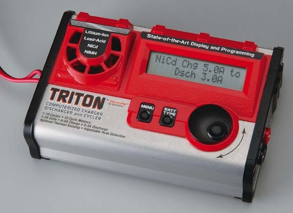 Great
Planes raises the anti in the $100-$200 charger range with their introduction of
the Triton.Behind the distinctive red plastic bezel the extruded aluminum case
contains some innovative features. As the hobby standard Ni-Cds are being
challenged by newer technology offered by Ni-MH and now Lithium-Ion/polymer
systems, the Triton presents a battery maintenance system that addresses these
new offerings.
Great
Planes raises the anti in the $100-$200 charger range with their introduction of
the Triton.Behind the distinctive red plastic bezel the extruded aluminum case
contains some innovative features. As the hobby standard Ni-Cds are being
challenged by newer technology offered by Ni-MH and now Lithium-Ion/polymer
systems, the Triton presents a battery maintenance system that addresses these
new offerings.
Item Tested - Triton
Computerized Charger, Discharger, Cycler
Purpose – Battery Maintenance
System
Manufacturer – Great Planes
Suggested Retail Price – $129.99
Warranty – One
year
Input Power -10-15V DC
Charge Range – 1- 24 Ni-Cd or Ni-MH, 1-4 Lithium Ion/polymer,
3-12 Pb (lead acid)
Fast Charge Rate – 100 mA to 5A - 90 watts max (2.5A max. for
Li-Ion/polymer)
Trickle Charge Rate – 30 to 250 mA – automatic (n/a for
Li-Ion and Pb)
Discharge Current - 100 mA to 3A - 20 watts max (2.5A max. for
Li-Ion)
Discharge Cut-Off - 0.5-1.16V/cell NiCd & NiMH,
Li-Ion/polymer 2.8V/cell, Pb 1.8V/cell
Cycle Count - One to ten cycles (n/a for Li-Ion/polymer
and Pb)
Battery Memories - 10
Dimensions – 6.2 x 4.0 x 2.0 in (157 x 102 x 51mm)
Weight - 16.4 oz (466g)
Instructions –19 6 X 8 ˝
pages – plus 5 program flow charts.
Tested On – Ni-Cd, Ni-MH, Pb (lead acid), Lithium
Ion/Polymer
CHEERS – The broadest range of
battery types served. Programmable voltage cut off, peak sensitivity, topping
charge and safety features. Banana plug connections on the SIDE of the charger
where they belong so as to not obstruct the display or controls. Once you are
over the initial learning curve, which is about the same as other units, the
Triton is faster to program.
http://www.electrifly.com/manuals/gpmm3150-manual-v1_1.pdf
For reasons known only to the instruction book authors,
charger purveyors feel bound to comment on the “Nickel Cadmium memory
problem” and what their unit does to address it and well as perpetuating other
popular battery myths. The Triton instruction manual is no exception. Just
ignore it in that regard, you won’t buy the Triton for the literary value of
the instruction book, but rather to maintain your battery packs. This is
accomplished quite nicely with the aid of the five programming flow charts that
were thoughtfully included with the product.Once you have the basics down these
programming charts are all you need for future reference.
Instruction book states that the Triton will shut down if
internal temperatures exceed 100° F. This is in error and should
read 100° C.
The fan does not turn on until needed, which occurs in the
following circumstances:
1. During discharge once needed.
2. During charge:
a. if the temp of the charger exceeds 50 degrees
centigrade
b. if the charge output power is over 30W
c. if the charge current is over 2.5A
d. if charging 1cell, or packs containing 2 or 3 cells
3. During charge or discharge, if the temp of the charger itself exceeds
100 degrees C the charger will stop all charge or discharge functions unitl the
temp of the charger becomes below than 70 degrees C. The fan should continue to
run unitl the temp of the charger drops below 45 degrees C. (We cover this in
the manual). In addition, once the fan turns on it should work until the
charge or discharge function is finished. If the temp of the charger still
exceeds 45 degrees C after a function is completed the fan should continue to
work until the temp drops below 45 degrees C."
 We
ran the usual performance tests on this unit using a digital multimeter with an
RS232 port connecting to a laptop. Old as well as new packs ranging from single
cells to the maximum of 24 were tested. Dozens of charge/discharge curves
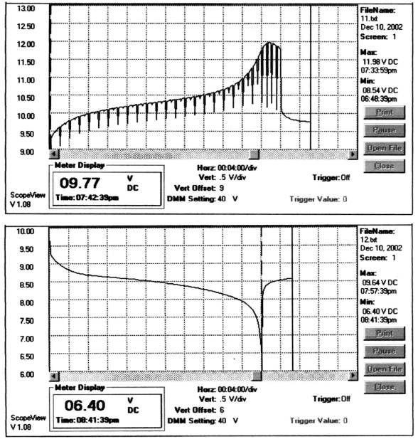
covering all the settings were accumulated. Charge and discharge curves (Figure
1) obtained from a well used 7 cell Cs electric flight pack are typical.
We
ran the usual performance tests on this unit using a digital multimeter with an
RS232 port connecting to a laptop. Old as well as new packs ranging from single
cells to the maximum of 24 were tested. Dozens of charge/discharge curves
covering all the settings were accumulated. Charge and discharge curves (Figure
1) obtained from a well used 7 cell Cs electric flight pack are typical.
Figure 1.
As the curves indicate, the Triton employs voltage-sampling
techniques that are pretty well standard in chargers of this type. Suffice it to
say that the testing verified the manufacturer’s claims and found them to be
an honest representation of the unit’s performance and capability. Voltage and
current readings were within 1% of those indicated by the unit.Based on time and
discharge currents the capacity readings were also well within reasonable limits
for a unit of this type.
Neat Features:
The people at Great Planes tried to cover all the bases and did a pretty good job.
If the buzzer annoys you it can be turned off – or set to any of 10 different melodies.
Pushing buttons – when and when not to.
The first thing that strikes you on this unit is that it
has two buttons and a combination rotary dial/push button, unlike the 4/6 button
arrangements seen on competitive units.I would have to temper the marketing
hype, “amazingly easy programming in almost no time”, to “it took me about
as long to get comfortable programming this unit as it did others I have
tested”. Thanks to another modeler, Darral Teeples <hdthc@juno.com> that
was also working his way through the amazingly easy programming, we
collaborated, comparing notes on the Triton’s operation secrets – when our
notes did not agree we isolated the problem to a slow switch (unit immediately
replaced by Great Planes) or in another instance to a low battery in a DVM
(that’s what that little flashing battery symbol means).
When you first connect the Triton to a 12 volt source you
get a few seconds of “GREAT PLANES ELECTRIFLY” then it goes to the charge
mode and rate of the last battery type you used with all of the settings you had
programmed for it.If this is what you want to do you simply depress the rotary
button for a few seconds and the charge process begins.If you want to change any
of the setup, depress the MENU button and rotate dial to what you want to set,
press the dial momentarily and then rotate to the setting you want, pressing the
dial once more to the setup where you can rotate to move to the next item. Once
you have made the any changes to the setup press the MENU button again to go to
the charge mode.
Five battery types (Ni-Cd, Ni-MH, Pb-lead acid, Lithium or
one of 10 battery memory setups) are selected by the BATT TYPE button, where you
can then set one of the 4 routines (charge, discharge, charge then discharge, or
discharge then charge) with the rotary button. Individual settings with these
charge rates, discharge rate etc. are set by pushing the rotary button
momentarily and then dialing the rate you want.
It is actually simpler to do than describe. Just follow the Programming Flow Charts.
Once you get use to it, the Triton is easier to program and
is certainly faster with the rotary dial feature to scan back and forth in the
various display screens.
While they tell you some of the features are available in
the Ni-MH mode only, you can cheat a little. Just set up for Ni-MH (set the peak
sensitivity for 10 mv) and then connect your Ni-Cd battery and start the
process. The Triton, smart as it is, cannot tell it is charging a Ni-Cd and will
allow you to use all the Ni-MH features.
Screw up protection.
Both input and output have reverse polarity protection and
in the case of the output connection gives you an error reading to inform you of
your sin. It also features an internal thermal protection that shuts the unit
down with an Overheating display if the unit internal temperature exceeds
a 100 degrees F. I didn’t check this out but heard one user complained that
where he flew it frequently got over 100 degrees – maybe Triton had the good
sense to warn the user as well as protect itself.
Overcoming the DC only stigma.Many chargers are
being offered that operate on DC only, while limiting them to 12 volts overcomes
the onerous UL certification process, many find that this restricts the utility
of the product. One does wonder how many people actually use the full features
and capability while the unit is connected to their car battery.The thought of
having to purchase a separate DC supply at $40 or more to use the cycler in your
shop is not appealing either.There is an inexpensive solution. It is found in
the power supply of your old PC, or if you don’t have an old one laying around
you should have trashed, you can get one at most any PC repair shop just for
carting it off. Once you have rescued the power supply drop by the Battery
Clinic www.rcbatteryclinic.com
where you will find a link to Pat Harvey’s excellent article on the conversion
details hosted by the Minnesota Area R/C Electric Flight
Enthusiasts.
The Triton may not be the ultimate in chargers in
this category, but it comes as close as the reviewer has seen to date.
Red Scholefield red@rcbatteryclinic.com 12-14-02
Return to Top of Page - Return to Building Techniques
Pattern Home Page | Rudder
Control | Max Points in Novice | Contests/Results
| Rebuild Fiberglass Fuse | Building
Techniques | Fuel Facts | Links